The following connection plans explain how Meteo-40 is connected with power supply, sensors and other periphery.
![[Note]](admon/note.png) | Note |
|---|---|
Since Meteo-40 is designed to be very flexible, various sensors can be connected to
the data logger. If the sensor you intend to connect, is not listed in this manual, refer
for technical details and connection plans shown on the data sheets on our website (
www.ammonit.com) or contact our sales team
(+49-30-6003188-0 or
|
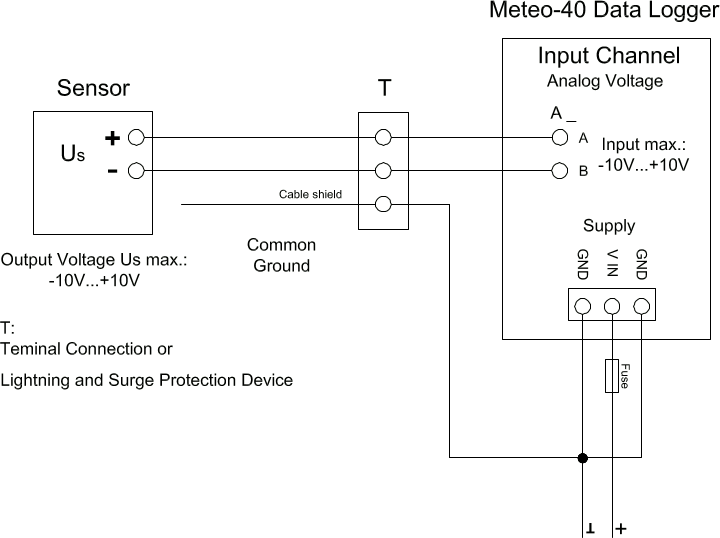
Floating voltage source (pyranometer) is connected via terminal or OVP to the differential analog voltage channels.
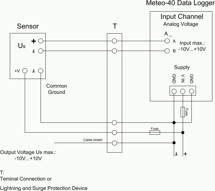
The temperature and/or barometric pressure sensor is connected via terminal or OVP to the differential analog voltage channels. To avoid ground loops, it is not recommended connecting the B terminal of the analog voltage input directly to common ground.
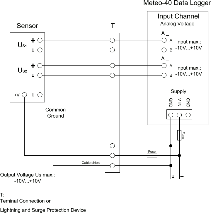
Voltage sources (temperature and humidity sensor) are connected via terminal or OVP to the differential analog voltage channels. To avoid ground loops, it is not recommended connecting the B terminal of the analog voltage input directly to common ground.
Figure 13.5. Electrical Connection Plan: Analog Voltage / Current Source (4-wire-connection; Pt1000)
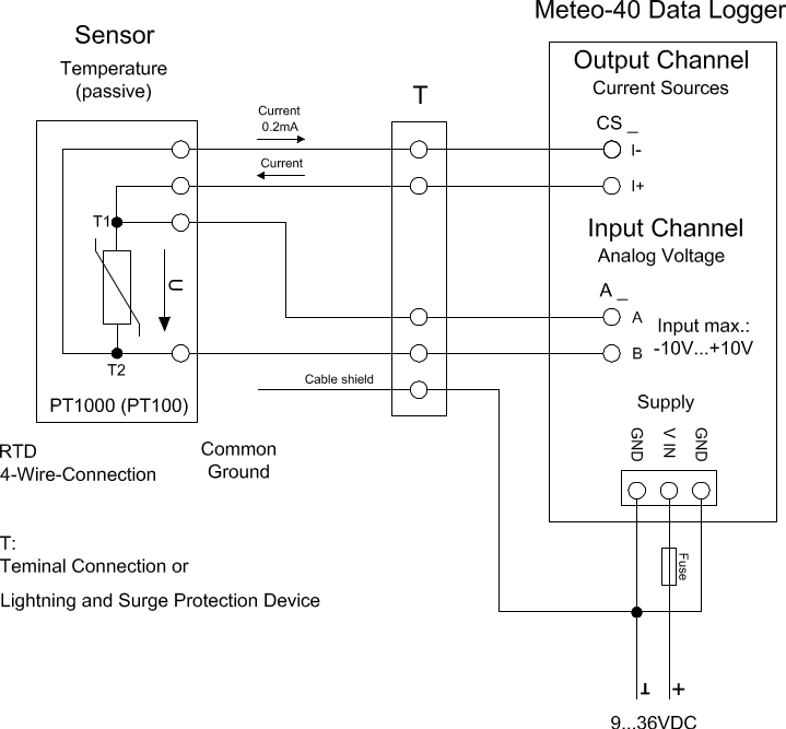
Analog Current Source (CS) of Meteo-40 is applied to feed a Pt100/Pt1000 temperature sensor. The sensor is connected via terminal or OVP to the differential analog voltage channel. 4-wire measurement is recommended to avoid voltage errors due to the resistance of feed line.
Figure 13.6. Electrical Connection Plan: Analog Voltage / Current Source (4-wire-connection; Pt1000 + Humidity)
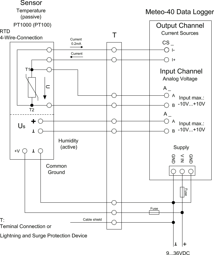
Analog Current Source (CS) of Meteo-40 supplies the Pt100/Pt1000 temperature sensor. The active humidity sensor may be fed by the same supply as the data logger. Both sensor outputs are connected via terminal or OVP to individual differential analog voltage channels.
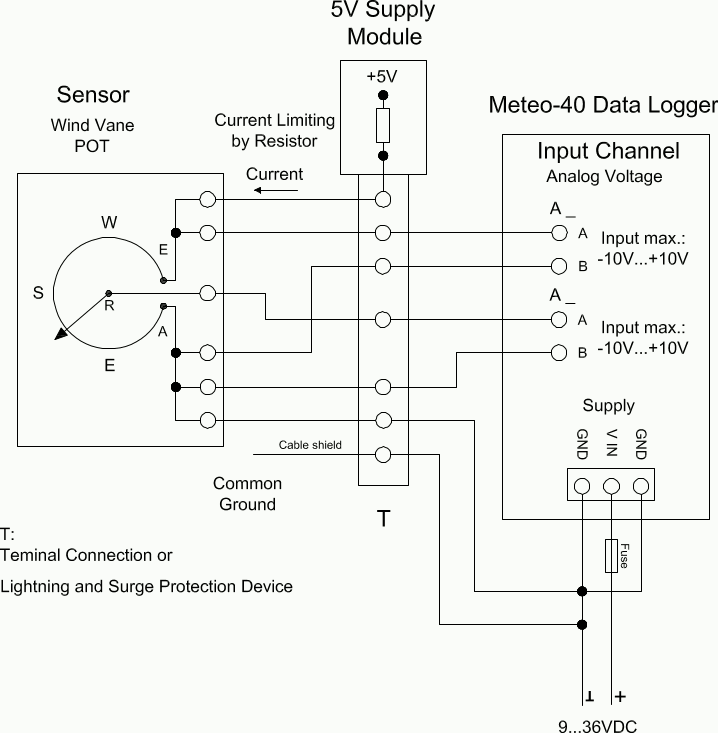
The figure above shows the 5-wire connection of a potentiometric wind vane. The intention of this configuration is to avoid voltage drops on the measurement lines caused by wire resistance. The first analog voltage channel measures the voltage across the whole potentiometer while the second channel measures the voltage between wiper and ground. The configuration is supplied via current limiting resistor by a 5 V supply. All lines to the wind vane are connected via terminal or OVP.
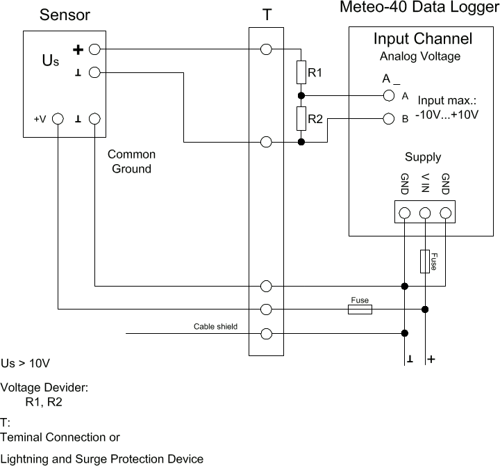
The Meteo-40 data logger is designed to measure analog DC voltages from -10 V–10 V. This is sufficient for most meteorological sensors. If voltages higher than +10 V occur, the voltage at the analog voltage inputs must be shared by a voltage divider. Note that R2 is in parallel to the input impedance of the analog voltage channel (1 MΩ).
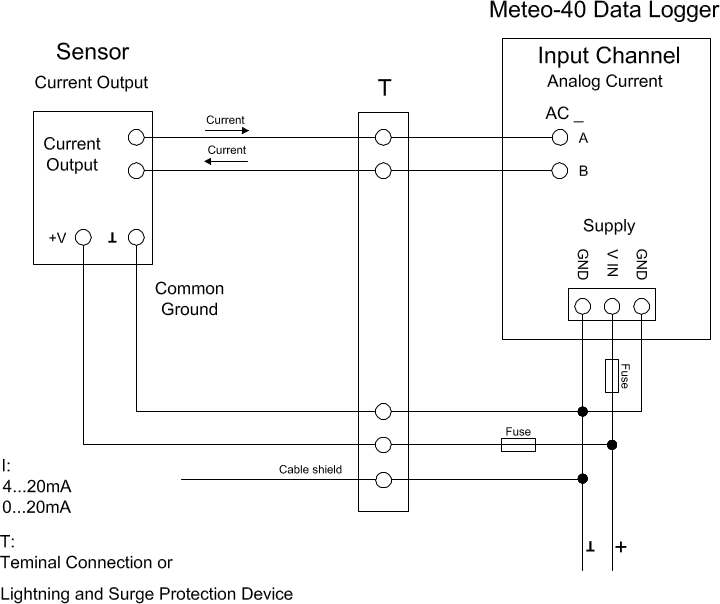
Meteo-40 comprises analog current measurement inputs (AC) to measure DC currents up to 100 mA. Many meteorological sensors provide analog current outputs with 0–20 mA or 4–20 mA. The positive signal line has to be connected to the A input. The negative line (or signal ground) has to be connected to the B input of the analog current input. The figure above depicts the recommended setup using connections via terminal or OVP to the data logger.
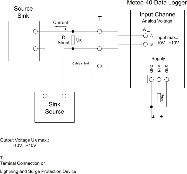
The Meteo-40 data logger can measure DC currents up to 100 mA on its analog current inputs. This is sufficient for most meteorological sensors. If currents higher than 100 mA are to be measured, a shunt can be used in conjunction with the analog voltage inputs.
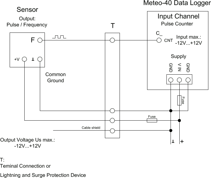
Meteo-40 comprises several impulse counter inputs (CNT). In most cases they are used for anemometer setup. The signal output of the sensor has to be connected to the CNT input of the data logger. To avoid floating signals common ground is used for the negative line of counter connection. The figure above depicts the recommended setup using connections via terminal or OVP to the data logger.
Figure 13.12. Electrical Connection Plan: Pulse Counter with Pull-up Module for Precipitation Measurement
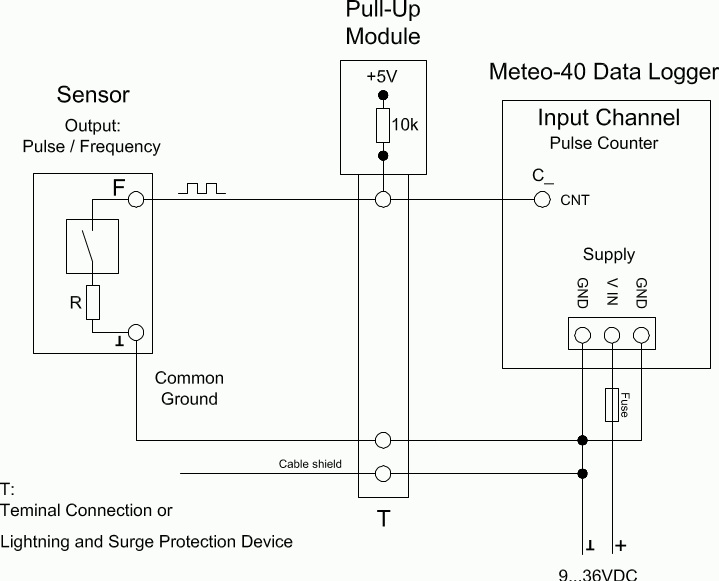
The counter inputs of the Meteo-40 data logger can be used for precipitation sensors. Most precipitation sensors comprise open collector outputs or use a switching reed contact. In both cases an additional pull-up resistor has to be applied. This pull-up resistor is tied to a 5 V supply to feed the sensor's output. The module M83570 by Ammonit comprises several configurable pull-up resistors and an internal 5 V supply. M83570 can easily be integrated in the setup of a steel cabinet. The figure above shows the recommended setup using connections via terminal or OVP to the data logger.
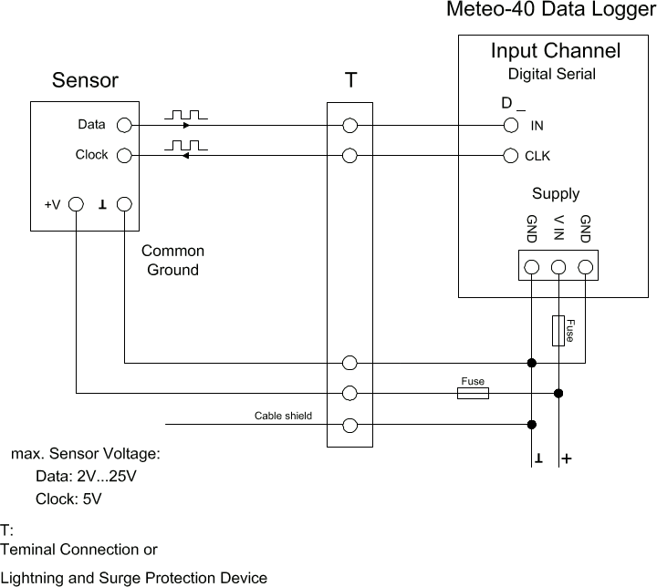
The Digital Serial inputs of Meteo-40 data loggers are designed to connect sensors using serial communication. The data logger sends a clock burst to the sensor via the CLK line. The response of the sensor is sent back to the data input line (IN) of the Digital Serial panel. It is essential that sensor and data logger use the same common ground. The figure above shows the recommended setup using connections via terminal or OVP to the data logger.
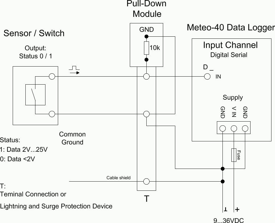
In some cases an additional pull-down resistor may be required to equalise the electrical potential on the status signal lines. This may be necessary to reduce perturbance caused by floating lines. The potential equalization can be realized by an external resistor to GND or an external module M83570 provided by Ammonit. This external module comprises pull down resistors for several signal lines.
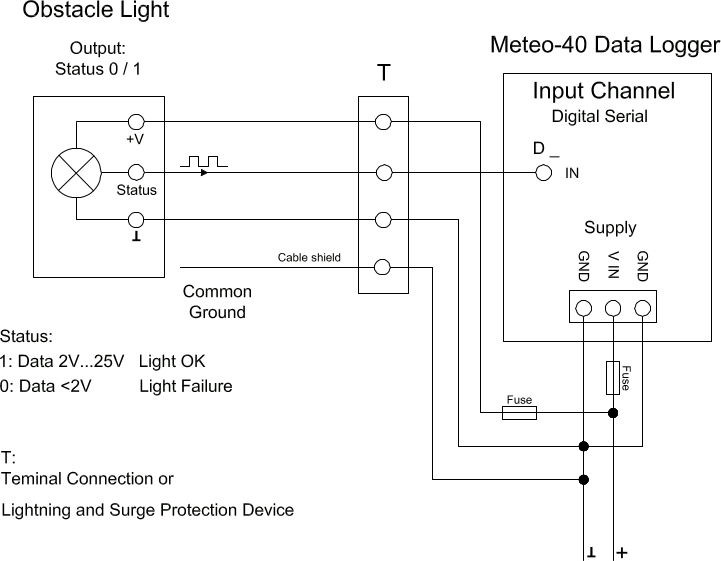
Many obstacle lights provide a diagnosis port to indicate malfunction. This diagnosis port can be connected to the IN port of the Serial Digital panel. For a detailed description of the electrical characteristics of the interfaces see table in Section 12.2.5, “Electrical Specifications of Digital Channels (Serial Input / Output)”. The figure above shows the recommended setup using connections via terminal or OVP to the data logger.
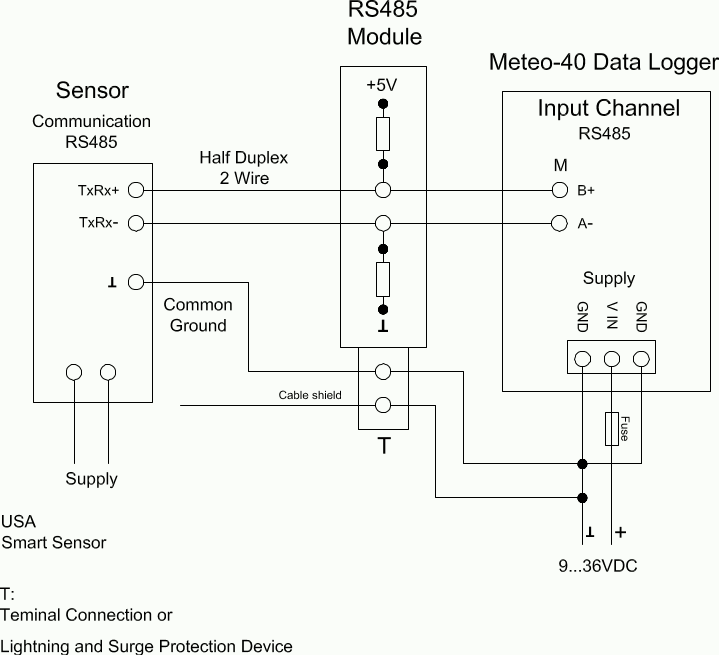
In case of RS485 bus communication an additional biasing may be required. This can be done with the configuration shown above. Ammonit provides the external Module M83570 which comprises a configurable circuit for biasing purposes. The M83570 module contains an internal voltage supply providing 5 V for biasing the RS485 bus lines.
Figure 13.17. Electrical Connection Plan: Switch external Sensor Heating via Meteo-40 Switch Manager
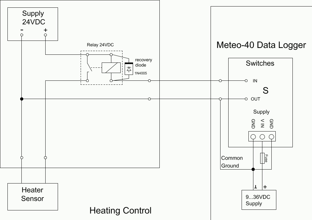
The configuration above displays the connection of an external sensor heating switched by the Meteo-40 heating control.