Chapter 1. Introduction
Table of Contents
1.1. Opening Remarks
Meteo-40 plus data loggers by Ammonit Measurement GmbH are professional measuring devices which record meteorological details in order to calculate the wind energy potential of a site. The data loggers can be used flexibly and are well-suited for a wide range of applications. The implemented standards of measurement evaluation and data security meet the requirements of professional specialists. However, you conveniently configure sensors, statistics and the communication via the user-friendly web interface.
Before installation read this manual carefully. Remember that time spent now setting up the data logger properly might save you from losing valuable data!
We recommend to configure and to test sensors and communication before the measuring equipment is installed on the mast.
We hope you find this manual clear and easy to understand. If you have any comments or suggestions, please let us know.
1.2. Overview of Meteo-40 plus
Depending on the model, Meteo-40 plus offers up to 34 measurement channels: There are up to 12 analog differential voltage inputs, up to 2 analog current inputs. Furthermore, Meteo-40 plus has up to 12 counter inputs and up to 8 digital channels.
In addition, Meteo-40 plus is able to support up to 8 smart sensors via the RS-485 interface.
In general, Meteo-40 plus is divided into two main units: A communication unit and a measuring unit. The communication unit offers 3 USB slots to connect a PC, modem, web camera, or flash drive, and 1 Ethernet slot to connect a camera or router. Additionally, the Meteo-40 plus can be connected to the network via Ethernet.
![[Note]](admon/note.png) | Note |
|---|---|
Meteo-40 plus Revision C offers a standard RS232 slot. Meteo-40 Revision D is equipped with an Ethernet slot. The production of Meteo-40 plus Revision C stopped in October 2012. Revision C is not supported anymore and cannot be upgraded to version 2 or higher. |
The basic concept is shown in detail in Figure 1.1, “Overview of Meteo-40L”.
Figure 1.1. Overview of Meteo-40L

1.3. Meteo-40 plus Series
The Meteo-40 plus series differs mainly in the number of input and output channels and in the measurement data storage capacity. Some basic information about the different models (Meteo-40S, Meteo-40M, Meteo-40L, and Meteo-40A) are shown in Table 1.1, “Meteo-40 plus feature overview”.
Table 1.1. Meteo-40 plus feature overview
| Feature | Meteo-40S | Meteo-40M | Meteo-40L | Meteo-40A | |
|---|---|---|---|---|---|
| Input channels | Counters | 4 | 8 | 12 | 2 |
| Periods | 0 | 2 | 4 | 0 | |
| Digital | 2 | 4 | 8 | 4 | |
| Analog (U) | 4 | 8 | 12 | 12 | |
| Analog (I) | 1 | 1 | 2 | 2 | |
| RS-485 | Up to 8 sensors | ||||
| Output channels | Switches | 2 | 4 | 8 | 4 |
| Constant Current | 1 | 1 | 2 | 2 | |
| RS-485 | 1 for SCADA | ||||
| Memory Size | Source Data | 1 GiB | 2 GiB | 2 GiB | 1 GiB |
| CSV Data | > 50 MiB | ||||
| Connectivity | USB | 2 USB host, 1 USB device | |||
| Ethernet | 1 for router, LAN | ||||
| Display and keys | LC display with backlight (4 lines each with 20 characters), five keys | ||||
| Power supply | 9 - 36 V (DC) | ||||
| Note |
|---|---|
The predecessor of the current Meteo-40 plus Revision D, Revision C, is equipped with a standard RS232 slot instead of the Ethernet slot. |
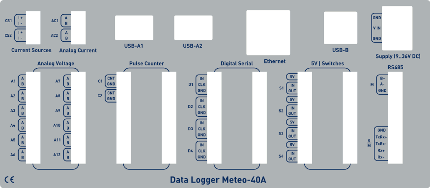
Find below an overview of the terminals. The white areas indicate available connectors.
Figure 1.2. Meteo-40L Terminal
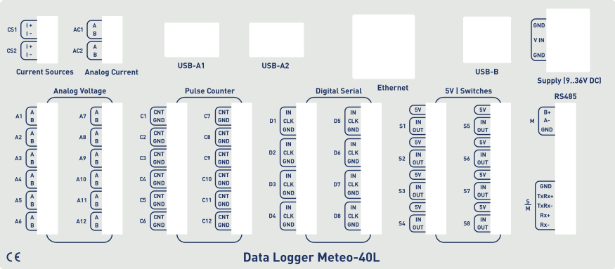
Figure 1.3. Meteo-40M Terminal
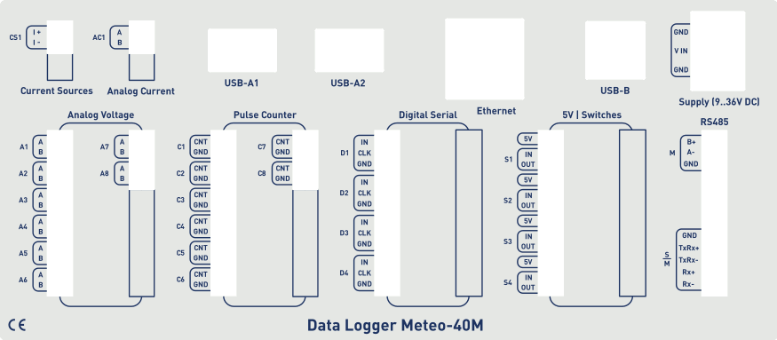
Figure 1.4. Meteo-40S Terminal
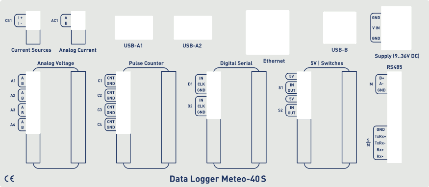
Figure 1.5. Meteo-40A Terminal
1.4. The Two Systems of Meteo-40 plus
Meteo-40 plus consists of two basic systems: the Measurement And Recording System (MARS) and the Configuration, Evaluation and Communication System (CECS).
For measuring and recording data, only MARS is needed. MARS is a 8-bit microcontroller designed to work with minimal power consumption. It controls the analog data logger hardware, measurement channels and data storage. It has no access to the display or to the devices that could be connected via USB or Ethernet (RS232 for Meteo-40 plus Revision C).
In order to use connected devices and to operate the display or the web interface, CECS has to be started. CECS is a fully operational embedded Linux™ computer with a 32-bit microcontroller. Starting it activates all Meteo-40 plus's features, but increases power consumption.
To save power during a measurement campaign, CECS is usually powered down and only MARS is running. MARS starts, when the power connector is plugged in.
The booting process of the MARS software is indicated by the illumination of the two lower LEDs (red and yellow). Both LEDs will turn off, when the MARS is started successfully.
CECS can be started either manually or automatically. To manually start CECS, press the middle button of the keyboard and hold it until the display turns on. A manual start of CECS is necessary for the initial configuration of Meteo-40 plus.
Later on, during a measurement campaign, CECS will be started by MARS according to the configured time schedule, e.g. to upload measurement data. After the scheduled actions have been executed, CECS turns off automatically to reduce power consumption.
Figure 1.6. Block diagram of Meteo-40 plus
1.4.1. CECS: Switch on / off behaviour
CECS is configured to run for 20 minutes, before it automatically turns off. When the time is expired and an action is still running, e.g. sending an email, the system will wait until the action is finished and will switch off afterwards. The remaining time is displayed in the status box (see Section 3.2, “Global Control Elements”) of the Meteo-40 plus web interface.
| Note |
|---|---|
With every user action, e.g. navigating the web interface or pressing a button on the keyboard, the remaining time will be reset to 20 minutes. |
For
SCADA
operation,
CECS has to run permanently. This is possible by means of the
CECS always active mode. If
CECS always active mode is selected, it will be displayed in the
status box (see
Section 3.2, “Global Control Elements”) in the web interface with the infinity symbol
(∞) as well as on the Meteo-40 plus
display with the word
Always.
| Note |
|---|---|
The
CECS always active mode is not selected by default. If the SCADA
server is activated, the
|
If power supply is disconnected and the data logger shuts down while CECS was running in the CECS always active mode, it will start automatically as soon as power is available again.
![[Important]](admon/important.png) | Important |
|---|---|
When CECS is configured to be permanently on, you cannot manually shut down the system by pressing the middle button on the data logger. |
1.5. Data Storage
CECS and MARS both have access to the measurement data storage, referred to as the shared source data memory. It is possible to view or download the source data via the web interface, see Section 6.7, “Access to Source Data”.
| Note |
|---|---|
For optimal data recording, it is recommended to format the data storage before starting a new measurement campaign. Formatting is a very fast process, which only takes a few seconds and can be performed via the web interface under the → menu. For further details see Section 4.2, “System Administration”. |
1.6. User Interfaces
There are two ways to control and configure the data logger: via web interface or by using the buttons of Meteo-40 plus. The second method is only intended for checking and testing, since this control menu provides only a limited number of configuration options. However, the web interface offers all available setup options and is recommended for the configuration of the device. To use the web interface a TCP/IP or USB connection is required.
Thanks to its web interface, Meteo-40 plus can also be operated via Internet with mobile devices, e.g. smartphone or tablet PC.
| Important |
|---|---|
The Meteo-40 plus web interface is accessed via HTTPS connection, which uses high-grade encryption (AES-256). This connection cannot be decrypted easily using today's technologies. |
1.7. Communication Methods and Required Devices
Depending on the project, Meteo-40 plus offers various methods for communication and data retrieval. All available methods are commonly used as well as easy to handle and to configure. In order to set up the connection to Meteo-40 plus, devices like Ethernet cable or modem are necessary as shown in the following table.
| Method / Action | Configuration | Software Update | Data Download | Required Devices | Comment |
|---|---|---|---|---|---|
| Meteo-40 plus (stand-alone) | no (only a few settings can be changed) | no | no | - | Using the display (see Section 4.5.1, “Display Access” and Chapter 9, Using the Display). |
| USB flash drive (connected to data logger) | no | no | yes | USB flash drive | Manual data download on pre-configured USB flash drive (see Section 4.2, “System Administration”). |
| LAN (data logger connected to LAN) | yes | yes (Internet access required) | yes (Data transfer via email, SCP/FTP/SFTP/FTPS, AmmonitOR or manual data download via web interface) | Ethernet cable | Recommended for initial configuration and software updates (see Section 2.3, “Connecting Meteo-40 plus via Ethernet to your LAN”). |
| WLAN (PC, laptop etc. connected to data logger's WLAN) | yes | no | yes (Download via web interface) | USB WLAN dongle | Recommended on site for maintenance (see Section 7.8, “Configuring WLAN”). |
| Point-to-Point Ethernet (data logger connected to PC) | yes | no | yes (Download via web interface) | Ethernet cable | PC has to be configured (see Section 2.4, “Connecting Meteo-40 plus to your Windows 10™ PC via point-to-point Ethernet connection”). |
| USB (data logger connected to PC) | yes | no | yes (Download via web interface) | USB (A/B) cable | Backup access. Driver file might be required (see Section 2.5, “Connecting Meteo-40 plus with your Windows 10™ PC via USB”). |
| USB (data logger connected to smartphone) | yes | yes, tethering function of the smartphone needs to be activated | yes (Download via web interface) | USB cable of the smartphone (accessory) | Convenient for remote servicing or software upgrades, when no modem is installed. |
| Modem access (data logger connected to modem, e.g. GPRS/GSM, directional radio, satellite) | yes | yes (Internet access required) | yes (Data transfer via email, SCP/FTP/SFTP/FTPS, AmmonitOR or manual data download via web interface) | Modem and accessory cable | Thanks to AmmonitConnect a standard SIM card can be used in a GSM modem. A SIM card with a static IP address is not necessary. (see Section 7.9, “Configuring the Modem”). |
| SCADA over RS-485 (Modbus RTU) | no | no | yes (Modbus protocol) | - | Modbus register map has to be configured for data retrieval (see Section 8.1, “Configuring Meteo-40 plus for SCADA”). |
| SCADA over Ethernet (Modbus TCP/IP) | no | no | yes (Modbus protocol) | - | Modbus register map has to be configured for data retrieval (see Section 8.1, “Configuring Meteo-40 plus for SCADA”). |
| Note |
|---|---|
If you are working with a Meteo-40 plus Revision C with RS232 slot, you need an USB Ethernet adapter to connect the data logger to your LAN. The production of Meteo-40 plus Revision C stopped in October 2012. |