Chapter 12. Technical Data
Table of Contents
- 12.1. Specification
- 12.2. Electrical Characteristics
- 12.2.1. Electrical Specifications of Analog Voltage Channels / Differential Inputs
- 12.2.2. Electrical Specifications of Analog Current Channels / Differential Inputs
- 12.2.3. Electrical Specifications of Counter Channels / Non-Differential Inputs
- 12.2.4. Electrical Specifications of Digital Channels (Serial Input / Output)
- 12.2.5. Electrical Specifications for Digital Clock Output
- 12.2.6. Electrical Specifications for Analog Current Source
- 12.2.7. Electrical Specifications for Switches
- 12.2.8. Electrical Specifications of the RS-485 Interface
- 12.2.9. Electrical Specification of the Ethernet Interface
- 12.2.10. Electrical Specification of the RS232 Interface
- 12.2.11. Electrical Specifications of Internal Measurements
- 12.2.12. Electrical Specification of the Power Supply
12.1. Specification
| Property | Specification | |||||
|---|---|---|---|---|---|---|
| Housing Dimensions | 260 × 194 × 50 [mm] | |||||
| Weight | 950 g | |||||
| Protection | IP65 | |||||
| Temperature |
| |||||
| Memory |
| |||||
| Date Format | YYYY-MM-DD | |||||
| Time Format | hh:mm:ss | |||||
| Clock |
| |||||
| Power Supply | No internal supply! (see Section 12.2.12, “Electrical Specification of the Power Supply”) |
![[Important]](admon/important.png) | Important |
|---|---|
Meteo-40 plus has no internal supply battery! External power supply is essential for proper operation. Section 12.2.12, “Electrical Specification of the Power Supply” contains the characteristics of the voltage supply and the current consumption of the data logger. |
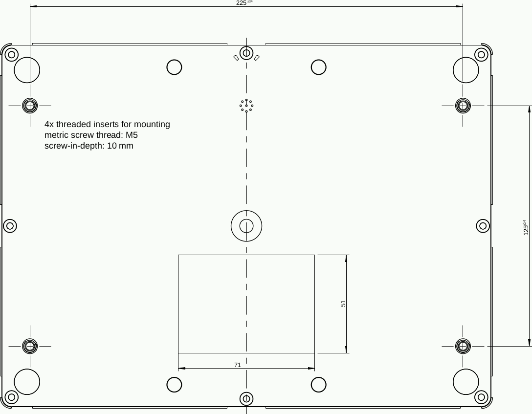
Figure 12.1. Mounting threads dimensions.
12.2. Electrical Characteristics
- 12.2.1. Electrical Specifications of Analog Voltage Channels / Differential Inputs
- 12.2.2. Electrical Specifications of Analog Current Channels / Differential Inputs
- 12.2.3. Electrical Specifications of Counter Channels / Non-Differential Inputs
- 12.2.4. Electrical Specifications of Digital Channels (Serial Input / Output)
- 12.2.5. Electrical Specifications for Digital Clock Output
- 12.2.6. Electrical Specifications for Analog Current Source
- 12.2.7. Electrical Specifications for Switches
- 12.2.8. Electrical Specifications of the RS-485 Interface
- 12.2.9. Electrical Specification of the Ethernet Interface
- 12.2.10. Electrical Specification of the RS232 Interface
- 12.2.11. Electrical Specifications of Internal Measurements
- 12.2.12. Electrical Specification of the Power Supply
The values given in the following tables
Table 12.1, “Electrical Specifications of Analog Voltage Channels / Differential
Inputs” to
Table 12.11, “Electrical Specification of the Power Supply”
contain the specifications of the digital
and analog inputs and outputs. The given values are specified for a temperature range of
-40 –
+65 °C.
![[Note]](admon/note.png) | Note |
|---|---|
All inputs and outputs are protected against overvoltage and electrostatic discharge using suppressor diodes. All voltage outputs of the data logger are fused by an self-resetting electronic fuse. Additionally, the power supply includes a reverse-polarity protection diode. |
12.2.1. Electrical Specifications of Analog Voltage Channels / Differential Inputs
Table 12.1. Electrical Specifications of Analog Voltage Channels / Differential Inputs
| Property | Specification | ||||
|---|---|---|---|---|---|
| Number of Channels per Data Logger Type |
| ||||
| Available Voltage Ranges (DC) |
| ||||
| Internal Resolution (Bit) |
| ||||
| Internal Resolution (Voltage) |
| ||||
| Measurement Accuracy (Voltage) |
| ||||
| Input Impedance | 1 MΩ | ||||
| Input Voltage |
| ||||
| Maximum Measurement Frequency | 4 Hz |
12.2.2. Electrical Specifications of Analog Current Channels / Differential Inputs
Table 12.2. Electrical Specifications of Analog Current Channels / Differential Inputs
| Property | Specification | ||||
|---|---|---|---|---|---|
| Number of Channels per Data Logger Type |
| ||||
| Available Current Ranges (DC) |
| ||||
| Measurement Accuracy (DC) |
| ||||
| Resolution (Bit) |
| ||||
| Input Impedance (Shunt) | 4.7 Ω | ||||
| Maximum Input Current | 150 mA | ||||
| Maximum Input Voltage | 0.75 V | ||||
| Maximum Measurement Frequency | 4 Hz |
12.2.3. Electrical Specifications of Counter Channels / Non-Differential Inputs
The counter counts impulses within a defined measurement timespan. This measurement timespan is derived from a precise timer signal with a precision of ± 5 ppm in the temperature range -40–+65 °C.
In case of a measurement timespan of one second the count of impulses is equal to frequency (Unit: Hz).
Table 12.3. Electrical Specifications of Counter Channels / Non-Differential Inputs
| Property | Specification | ||||
|---|---|---|---|---|---|
| Number of Channels per Data Logger Type |
| ||||
| Maximum measurable frequency | 65535/period in Hz | ||||
| Frequency Resolution [a] | 1/period in Hz | ||||
| Voltage Threshold (f > 1 Hz) | 0.22 V | ||||
| Input Voltage |
| ||||
| Period Measurement (Non-Differential Inputs) | Channels P1 (C5), P2 (C6), P3 (C11), P4 (C12) | ||||
[a] The frequency resolution depends on the measurement period setting. Longer period time setting results in higher resolution. Measurement period defines how often the signal frequency is measured per second. | |||||
12.2.4. Electrical Specifications of Digital Channels (Serial Input / Output)
Table 12.4. Electrical Specifications of Digital Channels (Serial Input / Output)
| Property | Specification | ||||
|---|---|---|---|---|---|
| Number of Channels per Data Logger Type |
| ||||
| Input Voltage Range (High State) | 2 V–25 V | ||||
| Input Voltage Range (Low State) | -0.5 V–0.6 V | ||||
| Input Resistance | ≥ 10 kΩ |
12.2.5. Electrical Specifications for Digital Clock Output
Table 12.5. Electrical Specifications for Digital Clock Output
| Property | Specification | ||||
|---|---|---|---|---|---|
| Number of Channels per Data Logger Type |
| ||||
| High State | 5 V | ||||
| Low State | 0 V | ||||
| Output Resistance | 100 Ω | ||||
| Minimal Load Resistance | 500 Ω |
12.2.6. Electrical Specifications for Analog Current Source
Table 12.6. Electrical Specifications for Anlog Current Source
| Property | Specification | ||||
|---|---|---|---|---|---|
| Number of Channels per Data Logger Type |
| ||||
| Nominal Current | 200 µA | ||||
| Tolerances | < 0.5 % | ||||
| Max. Resistance | 10 kΩ |
12.2.7. Electrical Specifications for Switches
Table 12.7. Electrical Specifications for Switches
| Property | Specification | ||||
|---|---|---|---|---|---|
| Number of Channels per Data Logger Type |
| ||||
| Switch Voltage Range | 5 V–28 V | ||||
| Max. Current Continuous Switch | 120 mA | ||||
| Peak Switch Current (2 s) | 400 mA | ||||
| Switch On Resistance | < 350 mΩ | ||||
| Switch Off Resistance | > 10 MΩ | ||||
| Max. Output Voltage of 5 V Output Terminal | 5.5 V | ||||
| Min. Output voltage of 5 V Output Terminal | 4.7 V | ||||
| Max. Output Current per 5 V Output Terminal | 15 mA |
| Important |
|---|---|
The Meteo-40 plus switches deliver 5 V output to supply peripheral devices inside the steel cabinet of the measurement setup. The 5 V supply is not intended to supply sensors connected with long cables due to the risk of damage caused by lightning strike. The 5 V outputs provide an electronic current limiter and an overvoltage protection. |
12.2.8. Electrical Specifications of the RS-485 Interface
Table 12.8. Electrical Specification of the RS-485 Interface
| Property | Specification |
|---|---|
| Supply Voltage RS-485 A, B | 5 V |
| Termination Resistor (Bus Termination) | 120 Ω |
| Maximal Transmission Rate | 1 MB/s |
| Note |
|---|---|
Biasing of RS-485 interface via external module M83570. |
12.2.9. Electrical Specification of the Ethernet Interface
| Important |
|---|---|
The Ethernet interface is only available on Meteo-40 plus Revision D. |
Table 12.9. Electrical Specification of the Ethernet Interface
| Property | Specification |
|---|---|
| Ethernet port (Meteo-40 plus Revision D) | 100 Mbit/s (100BASE-TX) |
12.2.10. Electrical Specification of the RS232 Interface
| Important |
|---|---|
The RS232 interface is only available on Meteo-40 plus Revision C. The production of Meteo-40 plus Revision C stopped in October 2012. |
Table 12.10. Electrical Specification of the RS232 Interface
| Property | Specification |
|---|---|
| Serial interface port (Meteo-40 plus Revision C) | Male 9-pin RS232 connector for connection to serial modem |
| Maximal Baudrate | 115200 Baud |
12.2.11. Electrical Specifications of Internal Measurements
Meteo-40 plus measures the Internal Supply Voltage and Internal Current of the data logger. These measurement values can be used for remote verification of the functionality of the data logger and are written to the source data and the CSV data files respectively.
Important Notes:
Internal Supply Voltage and Internal Current are recorded with 12 bit resolution only,
Internal Supply Voltage is measured directly behind a reverse polarity protection diode. This means the measured value is approximately 0.35 volt lower than the supply voltage at the logger's supply terminals.
12.2.12. Electrical Specification of the Power Supply
| Important |
|---|---|
Meteo-40 plus has no internal supply battery! External power supply is essential for proper operation. |
Table 12.11. Electrical Specification of the Power Supply
| Power Supply | Property | Specification | |||
|---|---|---|---|---|---|
| Supply Voltage Input (with Reverse Voltage Protection) | Supply Voltage Range | 9 V (DC)–36 V (DC) | |||
| Peak Supply Voltage (10 s) | 55 V (DC) | ||||
| Current Consumption | Average Current Consumption @ 12 V (DC) during measurement | ≤ 30 mA (P < 360 mW) | |||
| Average Current Consumption @ 12 V (DC) during communication |
| ||||
| Average Current Consumption @ 12 V (DC) with display illumination |
|
| Note |
|---|---|
When the CECS is switched off, no power can be drawn from the USB or Ethernet ports. When 5 V output ports (Switches) are used the load at these ports must also be taken in account when calculating the power consumption of the data logger. |