Table of Contents
- 7.1. Introduction
- 7.2. Configuring the Communication Schedule
- 7.3. Configuring Online Access
- 7.4. Configuration for using AmmonitOR
- 7.5. Configuring Email Parameters
- 7.6. Configuring SCP, FTP and SFTP Parameters
- 7.7. Configuring LAN Parameters
- 7.8. Configuring W-LAN
- 7.9. Configuring the Modem
- 7.10. Troubleshooting
Depending on the usage of Meteo-40, several communication methods are available:
Table 7.1. Data Transmission with Meteo-40
| Measurement Campaign | Power Plant Monitoring | Maintenance (Site) | Configuration (Office) |
|---|---|---|---|
|
Mobile Communiction (GPRS, UMTS)
Directional Radio
Satellite
USB Flash Drive |
Ethernet
RS485 |
Ethernet
W-LAN
USB cable |
Ethernet
W-LAN
USB cable |
The Meteo-40 web interface can be accessed via:
![[Tip]](admon/tip.png) | Tip |
|---|---|
To download measurement data without accessing the Meteo-40 web interface, a pre-configured USB flash drive can be used (see Section 4.2, “System Administration”). |
If Meteo-40 has been connected successfully to one of the above mentioned devices or
networks, it is shown on the data logger
display under the menu
Communication. USB and Ethernet connections are displayed in menu
→ → ; a connected modem in menu
→ → . W-LAN (WiFi) parameters are displayed in menu
→ → .
![[Note]](admon/note.png) | Note |
|---|---|
Although no USB device is connected, Meteo-40 displays one
|
Once the connection has been established, further settings can be configured via the web interface. There are different ways to collect data from Meteo-40:
Data transmission between Meteo-40 and PC can be automatic (one-way) or interactive (two-way). Automatic communication means that Meteo-40 sends CSV files by email or uploads data via SCP/FTP/SFTP. Once the actions have been configured, no further interaction is needed. Active communication implies an action by the user, e.g., accessing the web interface while Meteo-40 is online. If a modem is used, you can access Meteo-40 via a tunnel server.
Table 7.2. Automatic vs. Interactive Communication with Meteo-40
| Automatic Communication | Interactive Communication |
|---|---|
|
|
|
|
|
The settings for data transmission or online access can easily be configured via the Meteo-40 web interface in the → menu (see also Section 7.2, “Configuring the Communication Schedule”). CSV files, which include measurement data, are stored on the data logger and can be downloaded directly from the data logger, sent automatically via email to an address of your choice as well as CSV files can be uploaded automatically to an SCP/FTP/SFTP server of your choice.
In order to configure the settings for each communication method, use the menu items: Online, AmmonitOR, Email, SCP/FTP/SFTP, LAN, W-LAN and Modem.
| Tip |
|---|---|
We recommend using our online platform AmmonitOR to manage and monitor measurement data. To register and start using AmmonitOR, go to the AmmonitOR login page. |
Table 7.3. Ports used by Meteo-40
| Port | Direction | Configurable | Usage |
|---|---|---|---|
| 21/tcp (FTP) | outgoing | yes | file transfer from Meteo-40 to file server |
| 4040/tcp | outgoing | no | secure tunnel for Meteo-40 web interface |
| 4041/tcp | outgoing | no | secure file transfer from Meteo-40 to file server, e.g. AmmonitOR |
| 25/tcp (SMTP) | outgoing | yes | email transfer from Meteo-40 to mail server |
| 123/tcp+udp (NTP) | outgoing | no | network time protocol to set time and date |
| 443/tcp (HTTPS) | incoming | no | secure Meteo-40 web interface |
| 465/tcp (SSMTP) | outgoing | yes | secure email transfer from Meteo-40 to mail server |
| 502/tcp (Modbus) | incoming | no | Meteo-40 SCADA service |
Actions are processes, which the data logger performs according to the settings in the → menu. You select which action should be performed at which time and how often or how long during a day.
Meteo-40 turns on one minute before an action takes place and stays switched on as long as the action is running. The status box in the web interface informs about the number of running actions.
| Note |
|---|---|
If CECS is always active has been selected in the CECS power mode section of the → menu, Meteo-40 does not switch off automatically. Refer to Section 1.4.1, “CECS: Switch on / off behavior” for further details. |
Configuring the schedule includes defining the communication behavior during a day
and selecting on which weekdays an action should be performed. Each action starts
performing at its
Start Time and will be repeated according to the defined
Interval until the number of actions (
Quantity) is achieved or a new day begins (
00:00).
- Online
Indicates the periods, at which the Meteo-40 web interface can be accessed over the Internet. If configured, a tunnel connection is established.
Note Be carefully selecting the online intervals of the data logger. Connection costs can be very high depending on the communication method. In most cases up to three online intervals of 20 minutes are sufficient.
- AmmonitOR
Indicates, when and how often CSV files should be uploaded to an AmmonitOR account.
Indicates, when and how often emails with attached CSV file(s) should be sent. If necessary, CSV files are generated automatically before emails are sent.
- SCP/FTP/SFTP
Indicates, when and how often CSV file(s) should be uploaded to a configured server using SCP, FTP or SFTP. If necessary, CSV files are generated automatically before upload.
- Only generate CSV
Indicates, when and how often CSV files should be generated without sending or uploading them. Select this option to generate CSV files for the manual download via web interface or on USB flash drive. According to the configured statistics (see Section 6.3, “Statistic Data Files”), Meteo-40 generates CSV files on the selected days at the scheduled times.
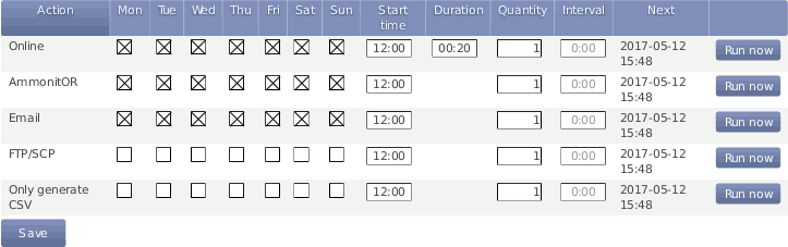
- Weekdays
Select the weekdays, on which the action should be performed.
- Start Time:
Determine, when the first action should start. If no Start time is defined, Meteo-40 will schedule the first action for
00:00.Enter the Start Time according to the 24-hour format:
hh:mm. Enter14:00, when the action should start at 14:00 hrs.- Duration (Only applies for Online):
Enter the length of time (hh:mm), which the data logger should be connected to the Internet. The duration begins with every start of an action.
Example: Start time
11:00, Duration00:20, Quantity 2, Interval03:00means that the data logger will be online at 11:00 hrs for 20 minutes. At 14:00 hrs Meteo-40 is online again for 20 min.Enter the Duration according to the following time format:
hh:mm.- Quantity:
Enter the number of actions, which should be performed during a day. Once a weekday has been selected to perform the action, the Quantity is set to
1. After changing the Quantity to a number higher than1, an Interval can be entered. The last action will be performed at the latest at midnight, even if the user's defined number of actions has not been achieved.Enter the Quantity as integer, e.g., 2, 3, 4.
- Interval:
Determine the time between the starts of two successive actions. The Interval can be entered once the Quantity of an action was set to a higher number than
1. Entering 01:00 means that the action will be performed hourly; entering 24:00 means that there is only one action per day possible.Enter the Interval according to the following time format:
hh:mm.- Next:
Displays, when the next action is scheduled indicating date and start time.
| Note |
|---|---|
Actions running just before midnight may be interrupted by the automatic CECS reboot. See Section 4.2, “System Administration” for details. |
For immediate action, click Run now. You can also start an action over the display menu (see Section 4.4.1, “Display Access”).
While Meteo-40 is online, the time elapsed is shown in the last column as percentage value. Otherwise, the Run now button can be clicked to connect Meteo-40 immediately to the Internet.
| Note |
|---|---|
Consider the time settings for sending emails and uploading CSV files via SCP/FTP/SFTP. During night hours the battery's energy might be too low to send or upload large files. |
Do not forget saving your modifications. Without saving the previous values will be reset.
| Tip |
|---|---|
In order to save or reduce connection costs, we recommend carefully setting the online periods of the data logger in the schedule. In most cases it is sufficient to configure not more than three time slots of 20 minutes for Internet activity. |
The Meteo-40 web interface can only be accessed remotely, when the data logger is powered-on and an Internet connection has been established. Periods for online access can be configured in the → menu.
![[Important]](admon/important.png) | Important |
|---|---|
Meteo-40 can be connected to a tunnel server (e.g., Ammonit Tunnel Server; see
Figure 7.2, “Communication between Meteo-40 and PC via Ammonit Tunnel Server”) to obtain a unique subdomain. Thus the
GSM modem can be equipped with a standard
SIM card with dynamic IP address. The tunnel server manages the
subdomains. Users access the Meteo-40 web interface (when online) by entering its
subdomain, e.g.,
|
A tunnel connection / tunnel server can be configured in the
→ menu. You can choose between the
Ammonit tunnel, your own
tunnel or
no tunnel, if you use Meteo-40 for testing purposes in your
office.
| Note |
|---|---|
If you use a SIM card with static IP address, a tunnel connection is not necessarily needed. The tunnel connection can be configured additionally, since it is established faster than the connection via static IP address. The Ammonit tunnel server caches images and history of the last sessions. |
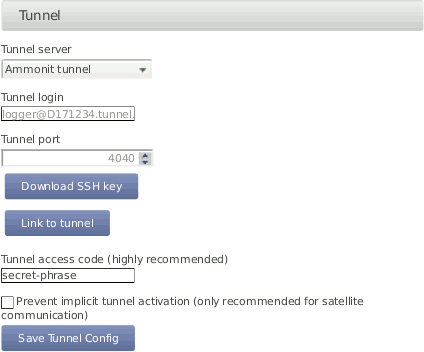
Meteo-40 offers three tunnel options (see Figure 7.3, “Configuring the Online Access”) in the → menu:
- No tunnel:
Select this option, when you use a SIM card with static IP address or when you are connected directly to the data logger via LAN (Ethernet) or USB.
- Ammonit tunnel:
Select the Ammonit Tunnel Server (see Figure 7.2, “Communication between Meteo-40 and PC via Ammonit Tunnel Server”) to access the data logger's web interface via an Ammonit tunnel domain link
https://Dnnnnnn.tunnel.ammonit.com).- Custom tunnel:
Enter Tunnel login and Tunnel port of your own tunnel server. Your server has to authenticate the Meteo-40 data logger. Download the SSH key of the data logger for authentication. Contact your system administrator for further details.
- Download SSH Key
Download SSH Key is only necessary, if you use your own tunnel server or an AmmonitOR installation. The SSH public key is used to authenticate the data logger at your server.
- Link to tunnel
In order to get the URL to access your Meteo-40 data logger via Ammonit tunnel, click on Link to tunnel.
- Tunnel access code
By using a Tunnel access code, you prevent unauthorized Internet traffic from reaching the data logger. This traffic might slow down your connection and increase Internet costs. For the tunnel access code, you can use upper and lower case letters, number, and the underscore. Other symbols are not allowed.
Tip By entering a tunnel access code, connection costs can be saved. The login page of the data logger is not visible for unauthorized users. Thus the URL of the data logger cannot easily be spammed or attacked.
Note Compared with the Tunnel affix(available in older Meteo-40 firmware versions), the Tunnel access code does not change the URL of your data logger in the tunnel. It remains https://dnnnnnn.tunnel.ammonit.com/.
Once the Tunnel access code has been entered in your browser, it is saved as cookie on your PC. The Tunnel access code has only be entered again on your PC after the cookie has been deleted.
| Tip |
|---|---|
By using the Ammonit Tunnel server with Tunnel Access Code, you can boost your connection to your data logger. The Ammonit Tunnel server recognizes the IP address of your data logger in the field. In some cases the IP address is accessible from outside (routable IP address of the installed SIM card). However, in this case you can directly access your data logger via its IP address. There is no need to use the circuit via the Ammonit Tunnel server in Germany. The Ammonit Tunnel server still manages the connection. Thus you access the web interface of the data logger via a simple URL: https://dnnnnnn-direct.tunnel.ammonit.com. This feature works with all Ammonit Meteo-40 data loggers, no matter which firmware version is installed. |
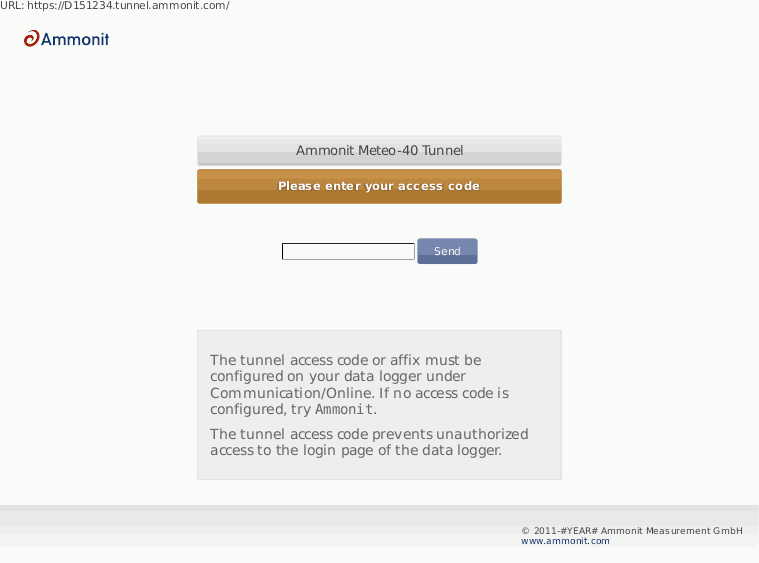
In order to access the data logger via tunnel, the URL of the data logger has to be entered in your browser, i.e., https://dnnnnnn.tunnel.ammonit.com/. On your first access via tunnel you have to enter the Tunnel access code, see Figure 7.4, “Entering the Tunnel Access Code”.
- Prevent implicit tunnel activation
The data traffic can be reduced by selecting this checkbox. The feature is especially designed for satellite communication. By activating the checkbox, the tunnel is only established according to the configured schedule (see Section 7.2, “Configuring the Communication Schedule”). Other tunnel activations are prevented.
| Important |
|---|---|
Meteo-40 can only be accessed via tunnel server, when the data logger is online! The online periods are configured in the → menu. |
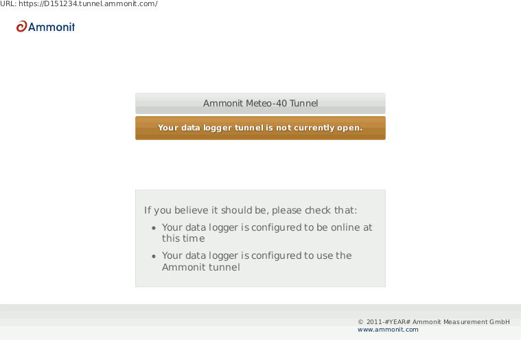
If Meteo-40 is configured for the Ammonit Tunnel Server and your data logger is currently not online, the following page (see fig Figure 7.5, “Communication via Ammonit Tunnel (closed tunnel)”) will be displayed.
- Remove tunnel identification
Public key cryptography is used at Meteo-40 to identify the tunnel server in order to prevent man-in-the-middle attacks. During the installation, Ammonit includes the ssh host fingerprint of the official tunnel server in the known hosts list of every data logger, to make possible the use of the tunnel service. If you are using a custom tunnel server, the new fingerprint will be added to the data logger known hosts list on the first access to your tunnel server. If the tunnel server ssh host key changes due to a server relaunch you must delete the old tunnel host identification in order to allow the connection.
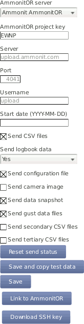
In the → the AmmonitOR server can be selected, and one can configure which kind of data is send to AmmonitOR.
If Meteo-40 user
Admin set the option
, the parameters cannot be changed by user
User.
| Note |
|---|---|
If you do not have an AmmonitOR account yet, go to the AmmonitOR login page or click on Link to AmmonitOR to register. Further details about AmmonitOR and a user manual can be found on www.ammonit.com. |
- AmmonitOR server
Select your preferred AmmonitOR server: Ammonit-hosted installation or your own AmmonitOR server.
If you use the Ammonit-hosted installation, server details are filled automatically. If you use your own installation, enter the necessary server details. Your local AmmonitOR server has to authenticate each data logger. To do so, see Section 7.4.1, “Authenticating Meteo-40 at your local AmmonitOR installation”.
- AmmonitOR project key
Enter the Project key of your related AmmonitOR project. The Project key is displayed in the project overview of your AmmonitOR project. It consists of four to six uppercase letters. You can connect more than one data logger to an AmmonitOR project. To do so, use the Project key for all project-related data loggers.
- Server, Port, Username
Name or IP address of your AmmonitOR server, TCP port, and username for upload. These values are automatically set correctly for the Ammonit hosted server.
- Start date
Files older than this date will not be transmitted to AmmonitOR.
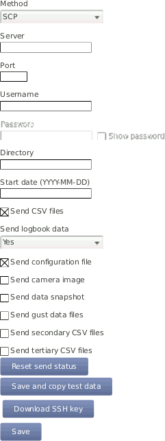
Decide, which data should be monitored in AmmonitOR:
AmmonitOR send options
- CSV files
Select this, if you want to send all measurement data to AmmonitOR.
If you do not want your measurement data sent to AmmonitOR, deselect this switch.
- Logbook data
Whether to send logbook entries. Select
Noto never send them,Yesto send them always on the next day, orImmediatelyto send them with every scheduled email.- Configuration file
Select this option, to send the data logger configuration file to AmmonitOR. Passwords and the modem PIN will be stripped of the configuration file for security reasons.
- Camera image
Select this option, to send camera images to AmmonitOR. The camera image is taken at the moment of the sending to AmmonitOR.
- Data snapshot
Select this option, to send data snapshots to AmmonitOR. The data snapshot consists of the measurements just in the moment of sending to AmmonitOR.
Note This feature is still considered experimental and might not always work.
- Gust data, secondary, and tertiary CSV files
Select this option, to send gust data, secondary, or tertiary CSV files to AmmonitOR.
Note This files are only stored on AmmonitOR, but not yet interpreted in any way.
- Reset send status
With this function, Meteo-40 forgets about ever sending files to AmmonitOR. Any files will be sent again.
- Save and copy test data
This function sends a test file to AmmonitOR. This is useful to check the connection and settings, such as the project key.
- Save
Save the current settings.
- Link to AmmonitOR
Click on Link to AmmonitOR to set up a new AmmonitOR account.
- Download SSH Key
Applies only, when you use a local AmmonitOR installation (not the Ammonit-hosted installation). Your AmmonitOR server has to authenticate each Meteo-40 data logger. To do so, download the SSH key and see Section 7.4.1, “Authenticating Meteo-40 at your local AmmonitOR installation” and AmmonitOR user manual on the Ammonit website.
If data files should be uploaded to a local AmmonitOR installation, the local AmmonitOR server has to authenticate each Meteo-40 data logger. To do so, download the SSH key from each Meteo-40 data logger. The SSH key can be downloaded in the → menu. Copy the SSH key on your local AmmonitOR server.
Open the AmmonitOR administration web interface (admin rights are necessary) and enter the SSH key in the → menu of AmmonitOR. For further details see AmmonitOR manual, which can be downloaded from the Ammonit website. After adding the key, the file upload can be configured.
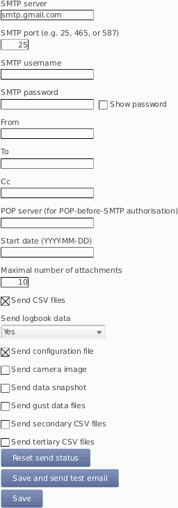
In order to receive data via email from the data logger, Meteo-40 has to be connected to the Internet (e.g., via modem) and an email account has to be configured in the → menu.
| Important |
|---|---|
Do not use your personal email account for data logger emails. We recommend setting
up a separate account. Anyone logged in as either
|
| Tip |
|---|---|
It is possible to use email addresses from free service providers, e.g., Yahoo, Gmail, to send data files from Meteo-40. |
Enter server and account details:
- SMTP server
Enter SMTP server address, e.g., smpt.mail.provider.com. SMTP (Simple Mail Transfer Protocol) is a standard protocol used to send emails. SMTP server details can be find in our email account data or contact your email service provider.
- SMTP port
Enter the SMTP port, e.g., 25 or 465, later servers often use 587. The port number can be found in the SMTP server details or contact your email service provider.
- SMTP username
Enter the username, which is used to access your email account. Often the username is the same as the email address.
- SMTP password
Enter the password, which is used to access your email account.
- From
Enter the sender's email address, which is often also the username of the email account.
- To
Enter the email address of the recipient. If more than one email address should be entered, use a semicolon (;) to separate the email addresses.
- Cc
If required, enter the recipient(s), who should receive the email in copy. If more than one email address should be entered, use a semicolon (;) to separate the email addresses.
- POP server (for POP-before-SMTP authorization)
Only required for SMTP servers using POP-before-SMTP or SMTP-after-POP authentication.
- Start date (YYYY-MM-DD)
Indicates which data files should be sent via email. No older files than indicated with the Start date will be sent.
Enter the start date in ISO-8601 format: YYYY-MM-DD (e.g., 2016-01-31)
All other send options are explained in the AmmonitOR section, AmmonitOR send options.
According to the settings in the → menu (see Section 7.2, “Configuring the Communication Schedule”), an email is sent to the specified account including one or more CSV files. An email includes all CSV files, generated since the last email has been sent.
| Note |
|---|---|
An email can include up to 10 attachments. If more files are to be transmitted, multiple emails are send. |
In certain cases it might be necessary to reset the status of the data files sent via email. The data files can be resend, e.g., to another email address or if old files have gone lost. Press Reset send status to set the send status of CSV files listed in the → menu to zero. The entered Start date indicates the data files, which should be reset for email transfer.
| Important |
|---|---|
Do not forget saving the settings. By clicking the button
|
| Note |
|---|---|
In order to test the email function, the data logger has to be connected to the Internet via modem, LAN or W-LAN (WiFi). It is not sufficient to connect Meteo-40 to a PC via USB, because a PC is not necessarily configured as router. If your smartphone is designed for tethering, you can connect your smartphone and configure it as router to test the email function of the data logger. |
On the Statistics Data Download page in the → menu all CSV files, which have been sent via email, have a checkmark. See also Section 6.3, “Statistic Data Files”.
Digital signature and encryption are very complex topics. By digitally signing an email or a file, its authenticity can be verified. A valid digital signature indicates that the email / file has been created by a known sender, e.g., your Meteo-40 data logger (authentication), and the email has not been manipulated on its way to the receiver (integrity). By using encryption, you can encode emails and attachments in a way that third parties cannot read the file, only authorized parties are allowed to open and read the files. A password is required to decrypt emails and files.
Read this section carefully and follow our description step by step to avoid any misunderstandings. For further details about digital signature and encryption, refer to Chapter 14, Cryptographic Software.
Meteo-40 integrates GnuPG, which is a free software to sign and encrypt data files. GnuPG is based on the international standard OpenPGP. Refer to Wikipedia or GnuPG website for further details.
In the → menu emails and attachments can be signed or signed and encrypted using GnuPG.
- Unsigned and unencrypted
If emails should be sent neither with digital signature nor password protected, select this option.
- Sign data (GnuPG)
Select this option to digitally sign CSV and logbook files sent via email. The CSV and logbook files sent by Meteo-40 are signed with a unique digital key. A certificate, indicating the digital signature, is attached to the email for each CSV and logbook file. The attachments can, however, be opened and saved without restriction.
As soon as a signed file is modified, the certificate is invalid.
In order to verify the certificate, download the
Public key, displayed in the Meteo-40 web interface and import the key into your local verification software, e.g., Gpg4win (see Section 7.5.1.1, “Working with Gpg4win to Decrypt and Verify Files on Windows™ PCs”).- Sign and encrypt data (GnuPG)
Select this option to sign (as above) and encrypt CSV and logbook files sent via email. Enter an Encryption password, which is required to decrypt the file on the recipient's side.
In addition to the digital signature Meteo-40 can encrypt CSV and logbook attachments with a
Private key. The encrypted files can only be opened by authorized persons with the Encryption password. To do so, additional software is required. See e.g. Section 7.5.1.1, “Working with Gpg4win to Decrypt and Verify Files on Windows™ PCs”.To decrypt the data, download the
Public keyby clicking on the button in the Meteo-40 web interface. Import thePublic keyinto your encryption software (see below). The displayedFingerprintis used to authenticate thePublic key.
In order to open and read files, which have been encrypted by Meteo-40, additional software is necessary. We recommend installing GPG4win (GNU Privacy Guard for Windows). Ggp4win enables users to encrypt, decrypt, sign and verify emails and attachments as well as files in a directory. The software includes the following components:
GnuPG: encryption tool
Kleopatra: certificate manager for OpenPGP
GpgOL: add-in for Microsoft Outlook 2003/2007/2010/2013™ for email encryption
GpgEx: plug-in for Microsoft Explorer™ for file encryption
Gpg4win Compendium: documentation for beginners and advanced users
Go to the GPG4WiN website and download the current software version. Install the software with the above mentioned components.
| Note |
|---|---|
If you work with Microsoft Outlook™, the program has to be restarted to implement the GpgOL add-in as separate ribbon. For decryption via the GpgOL add-in, go to Section 7.5.1.5, “Decrypting files in Microsoft Outlook™”. |
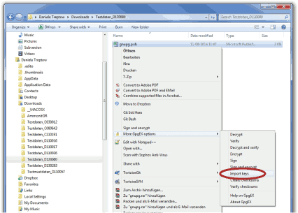
Before working with Gpg4win, the software has to be configured. Download the
Public key from the Meteo-40 web interface, as shown in
Figure 4.7, “Signing and Encryption”.
| Important |
|---|---|
Each Meteo-40 data logger has its own unique public key. If you work with different Meteo-40 data loggers, you have to import the public key of each Meteo-40. One user's private key is sufficient to certify the public keys (as shown in Figure 7.11, “Certifying the Public key”). |
Import the
Public key in Gpg4win via right-mouse click in the
Windows Explorer™. A message is displayed after successfully
importing the key.
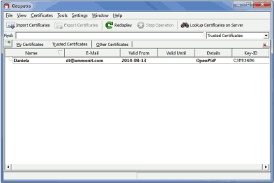
Open the Kleopatra software. The
Public key is listed under
Other Certificates.
The
Public key of the Meteo-40 data logger has to be certified by your
own key. If a user's private key has already been generated, skip the following task
and go on with
Figure 7.11, “Certifying the Public key”.
If no user's private key exists, create a new certificate via the → menu. Select Create a personal OpenPGP key pair and enter the required details. Click Create key and enter a high quality password. Your key should have been successfully created.
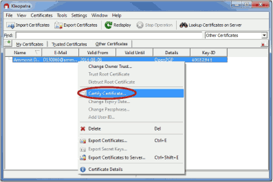
The
Public key of Meteo-40 has to be certified. Go to
Other Certificates and select Meteo-40's key. Open the context menu
via right-mouse click and select
Certify Certificate.
Before trusting the certificate, check the displayed
Fingerprint with the
Fingerprint shown in the Meteo-40 web interface (see
Figure 4.7, “Signing and Encryption”).
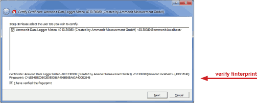
Verify the certificate and enter the password for the
Private key. The password is used to unlock the
Private key for the OpenPGP certificate. Finally both certificates
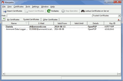
are displayed under
Trusted Certificates.
If
Sign data (GnuPG) has been selected, each CSV and logbook file sent
by Meteo-40 comes with a detached signature file, i.e., a separate signature file
(.sig) is attached to the email. The signature file has the same name as the CSV or
logbook file - ending on
.sig.
Download and certify the
Public key of Meteo-40 as described in
Section 7.5.1.1, “Working with Gpg4win to Decrypt and Verify Files on
Windows™ PCs”.
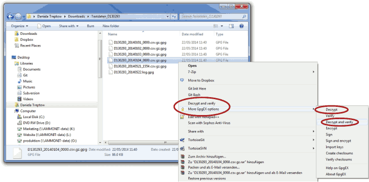
Download both related files to your directory. Choose the data or logbook file,
which should be verified. Open the context menu with a right-mouse click on the
.csv.gz,
.log or
.sig file and select
Verify.
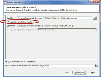
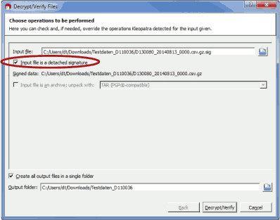
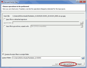
Make sure that
Input file is a detached signature is selected. Both related files
should be listed, with the signature ending on
.sig in the
Input file field. Select
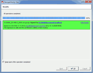
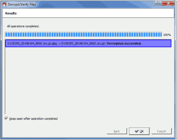
Decrypt/Verify. After verification the Kleopatra software
indicates the validity of the signature.

If
Sign data (GnuPG) has been selected, each CSV and logbook file sent
by Meteo-40 comes with a detached signature file, i.e., a separate signature file
(.sig) is attached to the email. The signature file has the same name as the CSV or
logbook file - ending on
.sig.
Download and certify the
Public key of Meteo-40 as described in
Section 7.5.1.1, “Working with Gpg4win to Decrypt and Verify Files on
Windows™ PCs”.
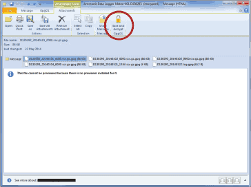
Open the email and select the file, which should be verified (ending on
.csv.gz or
.log). Click on
Save and decrypt in the
Attachments ribbon of
Microsoft Outlook™.
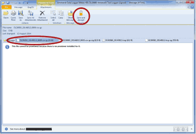
Make sure that
Input file is a detached signature is selected. Both related files
should be listed, with the signature ending on
.sig in the
Input file field. Select
Decrypt/Verify.
After verification the Kleopatra software indicates the validity of the signature.
| Note |
|---|---|
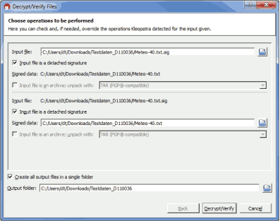
If test emails sent by Meteo-40 have been signed, a separate signature file is attached, e.g., Meteo-40.txt.sig. To verify the signature, open the email and select both related attachments, e.g., Meteo-40.txt and Meteo-40.txt.sig. Choose Save and decrypt in the Attachments ribbon of Microsoft Outlook™. Both files are listed in the Kleopatra software: Input file and Signed data (see Figure 7.19, “Verifying signed test mails”). Select Decrypt/Verify to validate the signature. |
Download and certify the
Public key of Meteo-40 as described in
Section 7.5.1.1, “Working with Gpg4win to Decrypt and Verify Files on
Windows™ PCs”.
Encrypted files can be decrypted in the Windows Explorer™. Right click on the file and select Decrypt and verify.
Start the decryption process by clicking Decrypt and verify.
For decryption enter the password, which you entered for encryption in the Meteo-40 web interface in the → menu.
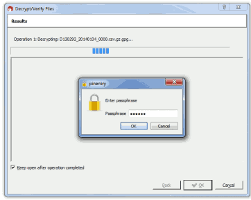
After successful decryption the file is displayed in the initial folder or the one selected in the decryption process.
After installing Gpg4win a new ribbon GpgOL should be shown in your Outlook™ application. Follow our step by step guide to decrypt encoded data files sent by your Meteo-40 data logger.
Download and certify the
Public key of Meteo-40 as described in
Section 7.5.1.1, “Working with Gpg4win to Decrypt and Verify Files on
Windows™ PCs”.
Open the email item and go to the Attachments ribbon (Click on one of the attached files). Click on Save and decrypt in the Attachments ribbon.
Select the folder, in which the files should be saved and start the decryption process by clicking on Decrypt/Verify in the Kleopatra software. For decryption, enter the passphrase that you configured for encryption in the → menu of the Meteo-40 web interface. See also Section 7.5.1.4, “Decrypting files in the Windows Explorer™”.
Both encoded and decrypted data files should be successfully saved in the selected folder.
| Note |
|---|---|
In order to verify signed and encrypted test emails sent by Meteo-40, open the email and select Decrypt in the GpgOL ribbon of Microsoft Outlook™. Enter the password, which has been set for Encryption in the Meteo-40 web interface at the → menu. |
By using SCP/FTP/SFTP you can upload CSV files to a server of your choice. To do so, Meteo-40 has to be connected to the Internet, e.g., via modem.
The CSV file upload can be configured in the → menu. Meteo-40 offers two methods to upload data:
If Meteo-40 user
Admin set the option
, the parameters cannot be changed by user
User.
- SCP
Select this option to upload files via SCP to your server. The connection is encrypted with RSA 2048 bit. Enter server address, port, username and directory to enable the file upload. Contact your system administrator for the server details.
SCP works only, if you add the data loggers public SSH key to the
authorized_keysfile on the server. SCP with login name and password is not supported. In doubt, ask your server administrator.All files uploaded via SCP have a checkmark in the SCP column in the → menu. See also Section 6.3, “Statistic Data Files”.
- FTP
Select this option to upload files to your FTP server. Enter server address, username, password and directory to enable the file upload. Contact your system administrator for the server details.
All files uploaded via FTP have a checkmark in the FTP column in the → menu. See also Section 6.3, “Statistic Data Files”.
![[Warning]](admon/warning.png)
Warning The file upload via FTP is not encrypted.
- SFTP
SFTP or Secure FTP is similar to SCP. In principal, the same facts apply.
By entering a Start date, you can configure which files should be uploaded. No older files than the indicated Start date will be uploaded.
All other send options are explained in the AmmonitOR section, AmmonitOR send options.
| Important |
|---|---|
Save your configuration. The entered values are reset after moving to another page. |
Each upload includes all collected CSV files, which have been generated since the last file upload. If it is the first upload, Meteo-40 uploads all CSV files - no matter, how many CSV files have been generated. The sequence of actions can be configured in the → menu. For further details refer to Section 7.2, “Configuring the Communication Schedule”
| Tip |
|---|---|
If you are using Windows™, you might try the FileZilla FTP server. After downloading and installing the software, you have to add a new user. Enter the appropriate fields and select the folder, which should be shared. It is also important to configure Windows™ Firewall by adding an exception for the corresponding port (21 for FTP) and the FileZilla server interface. |
| Warning |
|---|---|
Make sure to download FileZilla only from its official website or other trusted sources. Malicious versions have been released, that might copy private information to unauthorized parties. |
| Important |
|---|---|
Restart the data logger or disconnect the Ethernet cable for some seconds to apply new network settings. |
Meteo-40 data loggers can be connected to your LAN using a standard Ethernet cable.
The network connection will be automatically recognized. In order to access the Meteo-40
web interface, enter the assigned IP address
https://nn.nn.nn.nn/ in your web browser. The IP address can be found on
the data logger display by selecting the corresponding device at the
→ → → . Refer to
Section 2.3, “Connecting Meteo-40 via Ethernet to your LAN” and
Chapter 3, Login at Meteo-40 for more information about the login.
| Note |
|---|---|
If you are working with Meteo-40 Revision C with RS232 slot, you need an USB Ethernet adapter to connect the data logger to your LAN. The production of Meteo-40 Revision C stopped in October 2012. |
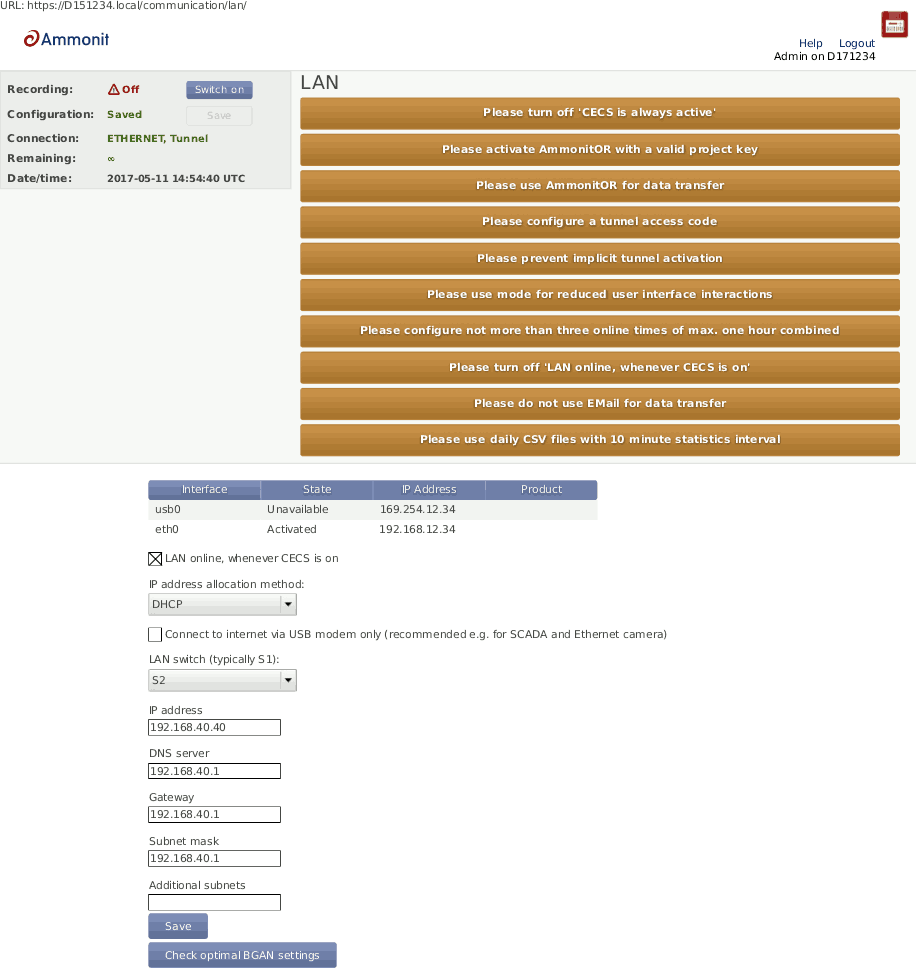
A table in the → menu displays, which devices are connected, e.g., USB and / or Ethernet with its state, IP address and product (if available).

- LAN online, whenever CECS is on
The checkbox is selected by default. Thus after connecting Meteo-40 to LAN via Ethernet, the data logger goes online as soon as the CECS subsystem is switched on.
- Use DHCP, static IP, or link-local
By default, Meteo-40 automatically obtains an IP address from a DHCP server. DHCP is active in most of the networks. If Use DHCP for wired network is active, the fields below are disabled.
For most SCADA applications, the data logger has to be configured with a fix IP address. Thus the use of DHCP server has to be deactivated. See Section 7.7.1, “Configuring a Static IP address in a LAN” for more information.
Note For upgrading the Meteo-40 firmware via the tethering function of your smartphone, the method has to be set to
DHCP. See also Section 4.3.1, “Upgrade using a Smartphone”.The
link-localmethod is useful for connecting a PC with Meteo-40 directly using an Ethernet cable. This connection will not have an influence over the USB modem communication and can be used for testing the former.- Connect to Internet via USB modem only (recommended e.g. for SCADA)
Select this checkbox to set the USB modem connection as preferred Internet connection. This checkbox is not selected by default.
This function is only recommended, when Ethernet port is used and USB-modem connections are preferred for the Internet connection, e.g., in SCADA applications or connecting a camera to the Ethernet port.
By choosing a LAN switch you can supply your router or modem, e.g., BGAN satellite modem. For further details about BGAN modems refer to Section 7.9.7, “Connecting a BGAN Satellite Modem to Meteo-40”.
In order to configure a static IP address in a LAN, go to the → menu and select Static IP. Enter the details for IP address, DNS server, Gateway and Subnet mask.
If the data logger has to be available from other subnets, e.g., if the SCADA Master is located in another network segment, it is possible to add additional subnets. The previously configured gateway will also be used for this subnets. A list of IP numbers and subnet prefixes can be entered in Additional subnets field. Use a semicolon (;) to separate the IP addresses, e.g., 192.168.13.0/24;192.168.14.0/24

| Note |
|---|---|
If you are working with a SIM card with static IP address, it is not necessary to change the LAN settings. Refer to Section 7.9.3, “Working with Static IP SIM cards”. |
For local wireless access to the data logger, you can connect a W-LAN (WiFi) USB stick to Meteo-40. Meteo-40 will create a wireless access point (hotspot) and you can connect to this network and access the data logger web interface.
Before using the W-LAN function, Meteo-40 has to be configured. Go to the → menu and select the checkbox Activate W-LAN. According to the configured IP address and Netmask, the available IP addresses range is shown.
| Important |
|---|---|
Note down or copy the assigned IP address, as you need this IP address to access the Meteo-40 web interface via W-LAN! |
Data loggers produced after 2017-05-12 have a default passphrase. The original WLAN passphrase is enclosed in the data logger's delivery. The passphrases are unique for each Meteo-40. If you prefeer to change this, you must enter a Passphrase consisting of at least eight characters. Click on Save to finish your configuration.
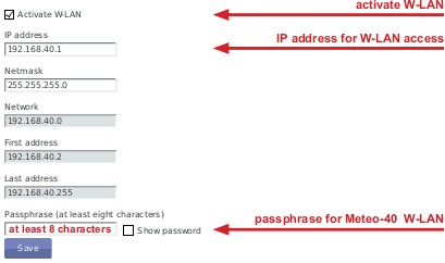
After successfully configuring the Meteo-40, the new wireless access point must appear among the available wireless networks at your computer. The new W-LAN name is the serial number of the data logger (Dnnnnnn). Select the W-LAN and enter the Passphrase.
Open your browser and enter the configured IP address (see Figure 7.28, “Configuring W-LAN Parameters”).
| Note |
|---|---|
If you are already connected to a W-LAN, a second W-LAN connection could cause problems. |
Meteo-40 can be connected to the Internet via modem to perform scheduled actions. UMTS/GSM/GPRS modems, or BGAN satellite modems can be configured. UMTS/GSM/GPRS modems are configured via the Meteo-40 web interface in the → menu.
| Note |
|---|---|
Depending on the SIM card used in the modem, a different APN (Access Point Name) has to be entered for proper communication. If you use a SIM card with dynamic IP address, you can easily configure the modem via our provider helper, see Section 7.9.1, “Using the Provider Helper”. If you use a SIM card with static IP address, an individual APN might be necessary. Ask your provider for the correct APN. See also Section 7.9.3, “Working with Static IP SIM cards”. |
In order to configure a BGAN satellite modem, refer to Section 7.9.7, “Connecting a BGAN Satellite Modem to Meteo-40”.
| Important |
|---|---|
We recommend configuring the modem in the web interface before connecting the modem to the data logger. |
| Tip |
|---|---|
If your SIM card gets lock for some reason, e.g., entering a wrong PIN code, remember the PUK code to create a new SIM card PIN code via the Meteo-40 web interface. See also Section 7.9.5, “Reset PIN Code of Locked SIM Card”. |
On the upper part of the configuration page, the properties of the connected modem are displayed, e.g., signal strength, operator, IP address and supported bands. If there is no modem connected, the fields are empty.

In the upper part of the screen, the current modem and connection properties are displayed:
- State
Connection status
- Reason
Reason of connection failure
- Signal
Signal strength
- Operator
Mobile network operator
- IP Address
IP address of modem
- Product
Product details
- RX/TX
Received/transmitted bytes
- Bands
Radio bands supported by the modem
Use the Provider Helper(see Section 7.9.1, “Using the Provider Helper”) to complete the required information or enter the details manually:
- Number:
Depending on your provider, the phone number of the GPRS/ UMTS or satellite service has to be entered, e.g.,
*99#.If you are using point-to-point protocol ( PPP, TCP/IP connection without GPRS or UMTS), enter the phone number in the relevant field. In this case, the APN is not important, but username and password probably are, depending on your provider.
In case of doubt contact your provider.
- APN (Access Point Name):
Enter the APN of the GPRS/ UMTS network, which can be requested from the provider or can be found in the Internet. CDMA does not require an APN.
Use the Provider helper to set APN and provider details automatically. Check the details with your provider. See Section 7.9.1, “Using the Provider Helper”.
Important If you are using a SIM card with static IP address, the APN is different from the one offered in the Provider helper. Ask your provider for the exact APN. See also Section 7.9.3, “Working with Static IP SIM cards”.
- Username:
Enter the username for the APN, if applicable.
The username will automatically be set by selecting the APN via the Provider helper .
- Password:
Enter the password for the chosen APN.
Password is automatically set after selecting the APN via Provider helper .
- Modem online, whenever CECS is on
The checkbox is selected by default. Thus the modem establishes an online connection as soon as CECS is switched on (automatically or manually). See also Section 7.9.4, “Two Ways to Establish an Online Connection via Modem”.
If the checkbox is deselected, the modem only turns on according to the defined actions in the schedule (see Section 7.2, “Configuring the Communication Schedule”).
Note The default setting with activated checkbox Modem online, whenever CECS is on can increase power consumption - depending on modem type and location of the next transmitting mast.
Tip By deactivating the checkbox Modem online, whenever CECS is on, connection costs can be saved. The modem will only be switched on according to the scheduled actions. A running CECS system for maintenance purposes does not switch the modem.
- Modem switch:
A switch can be selected for automatic control of modem power supply at the Modem switch combo box (see Section 4.6, “Configuring Switches”). An external relai will be controlled by the switch (see also Figure 13.1, “Meteo-40 Supply incl. Modem” for electrical connection plans). The modem will be power cycled as needed to prevent possible modem hangups.
Important If the modem is connected via relay to the data logger, a switch must be configured. Without selecting a switch for the modem, it will not be power cycled on data logger restart, e.g. after installing an upgrade or at the end of an action requiring communication. The assigned switch has to be saved to the data logger configuration. We highly recommend the usage of a modem switch, the modem may otherwise misbehave.
In Meteo-40 firmware version higher than 1.0 Rev.13915 switch S1 is set by default for the modem. If a different switch is used to control the modem relai, it must be accordingly selected. If the switch is not used for the modem, it can be deselected.
Note The switch configured for the modem supply is not available for sensor configuration.
Important If you use a BGAN satellite modem, a switch for the LAN connection has to be assigned in the → menu (see also Section 7.9.7, “Connecting a BGAN Satellite Modem to Meteo-40”).
- PIN:
Enter the PIN code of the used SIM card.
- New PIN:
This field is used, if you like or have to change the PIN. To use it, you need also to enter the PUK below.
- PUK
The PUK PIN Unlock Key (or Personal Unblocking Code, PUC) is used to activate the new PIN above.
- SMS
Click here to configure short message functions. See Section 7.9.2, “Short Message Service”.
After connecting a modem, Meteo-40 shows certain modem properties in its display in the → → menu. Use the right keyboard button to navigate to the modem properties. Additionally, you can see the properties such as state, signal strength and bands in the table (see Figure 7.29, “Modem Configuration”) displayed in the web interface in the → menu.
Apply the configuration by clicking on
Save. We recommend testing the modem connection. Therefore, activate
the checkbox
Modem online, whenever CECS is on. The state of the modem should
change to
Active, when the modem has been configured successfully.
Close the modem connection by deactivating the Modem online, whenever CECS is on mode. If no action is running, the modem connection is closed after 20 minutes from the last user interaction.
The connection will instantly be closed, when CECS is shut down in the → menu or when the modem is manually disconnected from Meteo-40.
| Important |
|---|---|
If you close the modem connection while accessing the data logger over the modem, you will instantly lose the communication with the data logger and you will not be able to access it until the next scheduled online action ( → ). |
Resetting the SIM PIN over the Meteo-40 web interface is only possible, when the SIM card has been locked after using a wrong PIN. SIM PUK and new PIN are required to unlock the SIM card.
In order to support users configuring modem settings, Meteo-40 offers a provider wizard, which can be started by clicking on Use provider helper. After choosing continent and country, the wizard shows available providers and APNs. Select the relevant APN and click on Finish to set APN, username and password in the modem configuration.
| Note |
|---|---|
The Provider helper is designed for SIM cards with dynamic IP address. For SIM cards with static IP address, refer to your provider to get the details for the modem configuration. See also Section 7.9.3, “Working with Static IP SIM cards”. |
The Provider helper does not fill in the number field. Enter number and PIN code manually to finish the modem configuration.

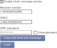
In order to configure the Short Message Service (SMS), go to the → menu and select .
| Important |
|---|---|
The Short Message Service on Meteo-40 data loggers can only be used in connection with a PHS8-P modem. Other modems offered by Ammonit do not support this feature. |
The parameters are:
- Enable short message service
Tick the checkbox to enable the SMS function of Meteo-40.
- Receiver number
This number is currently only used for sending test messages, i.e. one should enter the telephone number of a mobile phone. The number is not used for other SMS functions of Meteo-40.
- SMSC
The SMSC(Short message service center) has to be configured for some mobile telephony providers and SIMs, for others it is not necessary. In case of doubt, ask your mobile telephony provider.
- SMS password
Enter a password to use the SMS function. Without password the service is not possible. Use at least eight characters for the password (numbers and letters are allowed).
If the SMS feature is activated and a password has been entered, a message can be sent to the telephone number linked with the SIM in the modem. The content must be password command where password is the configured SMS password and command is an SMS command. Be careful typing the password respecting upper and lower cases.
Table 7.4. Short Message Commands
| Command | Description |
|---|---|
info or just
i, like
information | Meteo-40 replys to the short message with its serial number, software version, internal voltage, internal current, and internal temperature in that moment, and the current recording pointer, as well as state of switches, modem, and Ethernet. |
online or just
o, like
online | Meteo-40 tries to get online immediately and replys the same details as information. |
s
N
+ or
s
N
-, like
switch N on/off(
N corresponds to the switch number) |
Meteo-40 turns on or off the specified switch and replys the same details as information. E.g.:
|
| Note |
|---|---|
If you are unsure about the telephone number of the SIM or whether SMS sending works, try the function. |
If a SIM card with static IP address is used, refer to the configuration details given by your provider to complete the fields in the → menu. The APN for SIM cards with static IP address is different than for SIM cards with dynamic IP address. The Provider helper is designed for SIM cards with dynamic IP address.
| Note |
|---|---|
For testing the USB modem communication you can use a link-local connection over USB or LAN simultaeously. This connection will not have an influence over the usb modem communication. |
According to the actions scheduled in the → menu, Meteo-40 has to establish an online connection. To do so, CECS of Meteo-40 has to be switched on (see also Section 1.4, “The Two Systems of Meteo-40”). Meteo-40 offers two possibilities to set up or control the online connection via modem using the checkbox Modem online, whenever CECS is on:
- Modem is online to perform a scheduled action (checkbox inactive)
An online connection is established, when it is needed for an action, i.e., sending emails, uploading files or remote access according to the schedule (see also Section 7.2, “Configuring the Communication Schedule”).
- Modem is online, when CECS is running - independent of scheduled actions (checkbox is active; default)
An online connection via modem is established as soon as CECS(see also Section 1.4, “The Two Systems of Meteo-40”) of Meteo-40 is activated, either manually or according to the schedule in the → menu. The connection is closed, when CECS is switched off.
By default the Modem online, whenever CECS is on checkbox is activated and the modem always goes online, when CECS is running.
Important The default setting with activated checkbox can increase power consumption - depending on modem type and location of next transmitting mast.
We recommended deactivating this option, if the CECS always active mode (see Section 4.2, “System Administration”) is selected. With activated CECS always active mode, the modem will stay permanently online, despite the scheduled online actions.
The mode is independent from the LAN online mode.
If a wrong PIN code has been entered and the SIM card has been locked, use its PUK code to create a new PIN code. On the bottom of the modem configuration page you can find the appropriate fields (see Figure 7.29, “Modem Configuration”). Click on Save to apply the new PIN code, which will automatically be copied in the PIN code field for the modem configuration.
We recommend testing the modem connection before final installation in the field.
| Important |
|---|---|
In order to avoid PIN conflicts, we recommend configuring the modem before the modem is connected to Meteo-40. |
Before connecting the modem to Meteo-40 insert the SIM card into the modem. Afterwards the modem can be provided with power and connected to the data logger. If the modem has been successfully recognized, Meteo-40 shows the connection in its display → → .
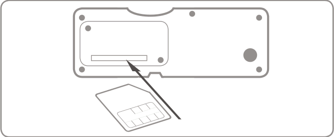
If you are using the modem Sierra Wireless AirLine Fastback Extend EDGE FXT009, slide the SIM card into the modem as shown in Figure 7.32, “Inserting SIM Card into modem Fastback Extend EDGE FXT009”.
| Important |
|---|---|
It is very important to lock the SIM card slot after inserting the SIM card into the modem. If the SIM card is not properly placed, connection problems may occur. |
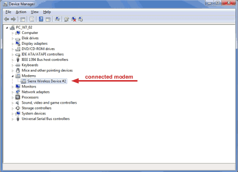
To customize the frequency bands of the modem, connect the modem directly to your computer via USB. If you are using a Windows™ PC and the modem is not displayed in the Device Manager under Modem, you require a driver file, which can be downloaded from the Sierra Wireless website. On Linux™ PCs, in general no driver file needs to be installed.
After connecting the modem to your PC, go to the Device Manager(see Figure 7.33, “Device Manager”) and open the properties of the modem by double-clicking on the modem.
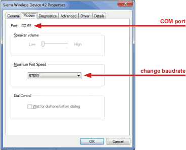
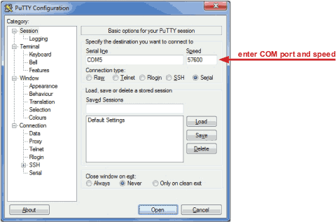
Go to the
Modem tab (see
Figure 7.34, “Modem Properties”) to get the name of the
COM Port, to which the modem is connected, e.g., COM5. Change the
Maximum Port Speed to
57600 baud rate. Save the changes.
To switch from one supported band to another, you can configure your modem with the help of AT commands.
AT+WMBS=5
(to switch to 850/1900 MHz)
|
AT+WMBS=4
(to switch to 900/1800 MHz)
|
AT+WMBS=7
(to switch to 850/900/1800/1900 MHz)
|
In order to customize the frequency bands, a standard terminal program like
PuTTY
can be used. Open the program and enter the port number as
Serial line and
57600 for the
Speed as shown in
Figure 7.35, “PuTTY Configuration”.
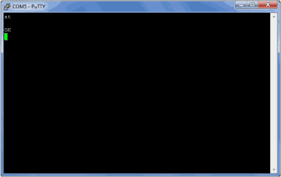
Open the command window (see
Figure 7.36, “PuTTY Command Window”) of the terminal program. In order to
test the connection, enter "
at" and press Enter. If
OK is shown, the connection is fine and you can change the frequency
bands with the above mentioned AT commands.
| Warning |
|---|---|
Make sure to download PuTTY only from its official website or other trusted sources. Malicious versions have been released, that might copy private information to unauthorized parties. |
| Important |
|---|---|
Restart the modem after modification. |
It is recommended to test the conectivity outdoors because pointing through a window introduces a slight drop in signal strength. Most units have audible and visual pointing indicators. The terminal first needs to acquire GPS, which may take a long time. Some units will then diplay pointing information to help with the orientation of the antena. Line-of-sight to the satellite is required for connectivity.
| Important |
|---|---|
BGAN modems are not configured using the modem page, but in the LAN page, as shown in Figure 7.26, “Configuring LAN parameters”. |
BGAN satellite modems are connected via Ethernet to Meteo-40. If you
are working with Meteo-40 Revision C with RS232 slot, you have to use an USB Ethernet
adapter to connect the satellite modem to your data logger.
Configure DHCP to automatically assign an IP address to data logger Ethernet port and modem. Both Meteo-40 and modem must be configured to use DHCP.
Use the software provided by its manufacturer to configure the
BGAN satellite modem.
In order to supply the modem, select a LAN switch from the dropdown list in the → menu. Hence prior to the scheduled actions, the modem can be supplied via the Meteo-40 switch (see Section 7.7, “Configuring LAN Parameters”). For testing, the checkbox LAN online, whenever CECS is on may be switched on. So the modem goes online as soon as CECS has been switched on. After testing, this setting should be switched off to prevent excessive traffic.
For testing the satellite modem, go to the
→ menu and press
Run now for the online action. Go to the
→ menu and copy the Ammonit tunnel address of the data logger, e.g.,
https://dnnnnnn.tunnel.ammonit.com. Disconnect the data logger from
your PC and / or LAN. After entering the copied address in your browser, you should be
able to log into the Meteo-40 web interface.
Use the
Check optimal BGAN settings button to verify if all recommended
settings are propperly configured.
We strongly recommend sending data only to AmmonitOR, but not by email. The data transfer to AmmonitOR consumes less bandwidth than email (see Section 7.2, “Configuring the Communication Schedule” and Section 7.4, “Configuration for using AmmonitOR”).
Use only few tunnel connections, e.g. twice or thrice a week for twenty minutes (see Section 7.2, “Configuring the Communication Schedule”).
Use a tunnel access code to prevent unauthorized access to the data loggers login page (see Figure 7.3, “Configuring the Online Access”) which can generate data traffic.
Only for software versions before
1.7.7: To reduce data traffic when using the web user interface, you may want to reduce user interface interactions (see Figure 7.3, “Configuring the Online Access”).Prevent implicit tunnel activation, only recommended for satellite communication (see Figure 7.3, “Configuring the Online Access”).
Do not set the check on LAN online, whenever CECS is on(see Section 7.7, “Configuring LAN Parameters”).
Be sure to generate not too huge or too many CSV files by keeping the default of one file per day with 10 minutes statistics interval (see Section 6.3, “Statistic Data Files”). Avoid gust data files, which may get large, depending on configuration and wind conditions.
Some mobile service providers and also firewalls in corporate networks restrict the communication of mobile devices to certain ports. The communication of the Meteo-40 data logger might also be affected. There are different incidents, e.g., the tunnel connection does not work, but Rx/Tx traffic is possible or the tunnel is accessible, but sending emails does not work. Reasons for this are often blocked ports by the communication service provider or the firewall or broken DNS.
In the web user interface, just save the online/tunnel parameters or AmmonitOR settings. In this moment the data logger checks the connection and presents the result.
Alternatively, you can do the check from the LC display. Go to
Communication(
Figure 7.38, “Select "Communication"”). Then select
Communication Check(
Figure 7.39, “Select "Check Connection"”). This will take some time. After some
seconds, you can see the results (
Figure 7.40, “View results of check”).
Figure 7.40. View results of check
                Tunnel accessible
Port 4040 open
AmmonitOR accessible
Port 4041 open
If one of the servers is not accessible or a port is blocked, please contact your network administrator or mobile service provider.