Table of Contents
This page gives an overview of important system properties, such as data logger type, serial number, available memory, software versions and number of channels.
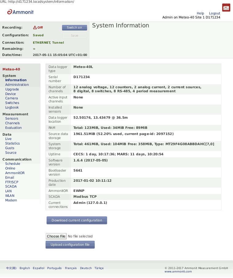
Under
Current connections all current logins are displayed with IP address,
e.g., via LAN, W-LAN (WiFi), USB or tunnel. If a connection has been established via tunnel
(see also
Section 7.3, “Configuring Online Access”), the letter
T after the IP address indicates the tunnel.
Source data storage shows the amount of memory which is already in use for storing source data. Please note, that more than 100 % are possible. A value beyond 100 % means that the data logger is overwriting the oldest source data by storing new data.
Use
Download Current Configuration to download the configuration file. The
configuration file is an
INI file, which is a widely-used
file format. This file contains configuration settings related to modem, Ethernet, server
upload, email, data evaluation, SCADA as well as activated channels and sensors. By saving
a configuration file, the configuration can quickly be uploaded and effectively applied to
other data loggers. The file name is
config-Dnnnnnn.txt with Dnnnnnn as the serial number of the data
logger.
![[Warning]](admon/warning.png) | Warning |
|---|---|
Be careful with uploading a changed INI file to the data logger. Inconsistencies can lead to malfunctions of the data logger. We strongly advice not to change manually any entry in the configuration file. |
This page contains different administration aspects of the data logger. Only users
logged in as
Admin can access the complete functionality of this section. If you are
logged in as
User,
Viewer or
Guest, changes in the
→ menu are not possible.
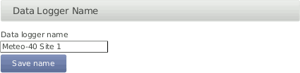
- Data Logger Name:
By giving each Meteo-40 a name, the data loggers can be identified easier. The name appears in the source data files header, on AmmonitOR and in the
config.txtfile.![[Note]](admon/note.png)
Note The data logger serial number is the most important ID to identify the data logger. Use the Data Logger Name to give the data logger a custom name, e.g.
Meteo-40 Site 1.- CECS Power Mode
The standard operation mode keeps CECS running for 20 minutes. Each user interaction resets the remaining time before automatic shutdown to 20 min. The CECS always active mode is not selected by default.
In order to keep CECS permanently running, e.g., for SCADA wind farm monitoring, Meteo-40 offers the CECS always active mode. This mode prevents the automatic shutdown of CECS. It can be configured via web interface ( → ) or by using the display( → ) of the data logger. To do any changes of the CECS mode via display, permissions have to be defined in the web interface ( → (see Section 4.4.1, “Display Access”). If the CECS always active mode is selected, it will be displayed in the status box of the web interface with the infinity symbol (∞) as well as on Meteo-40 display with the word
Always.Note If the power supply for Meteo-40 is disconnected while CECS is running in the CECS always active mode, CECS will restart automatically as soon as Meteo-40 is powered again.
To ensure reliability of Meteo-40 function, it is highly recommended, that the CECS is rebootet regularly. In cases, where CECS is always on, e, e.g. for SCADA, Meteo-40 has an automatic reboot function. The default behavior of Meteo-40 is to reboot just before the start of the week, i.e. every Sunday five minutes before midnight. Alternatively, you can choose to reboot every day five minutes before midnight, or never.
To restart the CECS, click on Restart CECS.
To shutdown the CECS, e.g., during remote access, click on Shutdown CECS.
![[Important]](admon/important.png)
Important When CECS is configured to be permanently active, you cannot shut down the system, neither by pressing the middle button on the data logger nor using the Shutdown CECS button at the web interface. You can still restart the CECS with the Restart CECS button.
Important MARS(for measuring and recording) continues without stopping during the restart. You will not loose any measurement data unless the recording is explicitly switched off or the power supply has been disconnected. For further details about the systems refer to Section 1.4, “The Two Systems of Meteo-40”.
You can start the CECS by applying a voltage peak to the selected digital channel. The voltage peak can be triggered over a cable / switch close to the ground. If this is prepared during the first installation, you might prevent further climbing up the met mast during maintenance work.
Once the CECS is on, the communication can be established remotely by any of the previously installed and foreseen methods (Modem, a previously connected Ethernet cable or WLAN). The CECS will automatically turn off after 20 min, if no action on the data logger is performed.
The voltage peak must last at least one second (see also Section 12.2.5, “Electrical Specifications of Digital Channels (Serial Input / Output)”). The digital channel has to be selected from the list of available digital channels in the Power CECS on digital status signal dropdown list. This change on data logger's configuration will stop the measurement for some seconds, until it is automatically or manually restarted (see Section 3.2, “Global Control Elements”).
- Date and Time, Location:
Time synchronization of the data logger is a primary concern. Four synchronisation methods are available: GPS, NTP, SCADA and Manually.
In order to synchronize date and time automatically to NTP servers, select Set data and time automatically. Additionally the time zone has to be set.
Warning It is not recommended to perform time zone changes during the measurement campaign. This could lead to duplicated measurement intervals and eventually data loss. We recommend to process the data later in AmmonitOR.
Optionally, you can also choose to Set date, time and location using GPS. The GPS device must provide a sentence following the GPRMC NMEA standard (e.g. PHS8-P modem).
To synchronise date and time over SCADA see Section 8.2.2, “Holding Registers”.
If date and time should be set manually, enter date (date format
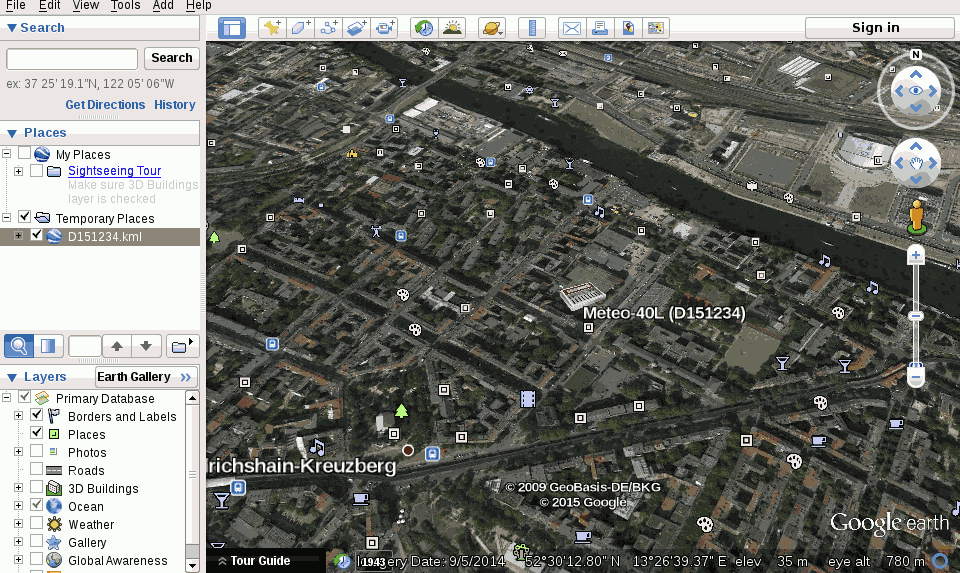
YYYY-MM-DD) and time (time formathh:mm:ss) in the appropriate fields. Date and time format are validated while typing the values.In order to view the data logger location in GIS programs or Google Earth™, you can set the data logger location (not altitude) either automatically via a GPS device, or manually by entering latitude, longitude, and altitude in the appropriate fields. Enter latitude and longitude in the decimal format (
dd.dddddd°), not in degrees and minutes (dd°mm.mmmm′, like GPS) nor in degrees, minutes, and seconds (dd°mm′ss.ss″).After downloading the KML file, you can open the file in Google Earth™.
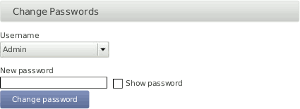
- Change Access Passwords:
User access passwords can be changed here. To do so, select a user name (role) from the drop-down list and enter the new password.
Warning Be aware that due to security reasons it is not possible to reset passwords. If you loose a modified
Adminpassword, there is no way to recover it, not even for Ammonit. In this case, return the data logger to Ammonit. Only Ammonit is able to restore the original passwords.Note Only the first eight characters of the password are significant, i.e.,
Ammonit_1andAmmonit_2would be treated the same. Eight characters give the choice of at least 10¹⁶ variations.- Signing and Encryption
Files sent by Meteo-40, such as CSV data or logbook files, can optionally be digitally signed or encrypted using GnuPG. The signature guarantees, that the files have been really produced by a specific data logger and have not been altered. The encryption ensures, that nobody can see the contents of the files without the right password.
For additional security, the user
Admincan set the option . If this option is set, users other thanAdminhave only restricted access to measurement data:CSV files can only be downloaded in encrypted form.
CSV files can only be copied to USB flash drive in encrypted form.
Live data can be seen only for 2 minutes on the web interface, but still unlimited on the LC display.
Source data cannot be downloaded nor copied to USB flash drive.
Data transfer settings (AmmonitOR, Email, SCP/FTP/SFTP, SCADA) cannot be changed.
Note The signature for a CSV file refers to the canonical, uncompressed CSV file. Before version
1.4.2, the signature referred to the compressed CSV file as sent by the data logger, however.Note If the Meteo-40 data logger has been produced before 2014-08, the digital signature is not available, only encryption (since firmware version 1.0.1). Please contact Ammonit, if digital signature is required on a previously purchased data logger.
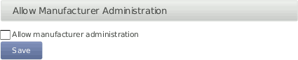
- Allow Manufacturer Administration
In some cases it is necessary that Ammonit developers have access to your data logger to check configurations or to modify any settings. The mode is only used for maintenance purposes. Activate the manufacturer administration mode to allow Ammonit developers accessing your data logger.
By default the manufacturer administration mode is inactive.
If the manufacturer administration mode is activated, you can start the manufacturer tunnel communication with the 'Start' button.
Important Without your permission, Ammonit will never access any of your data loggers!
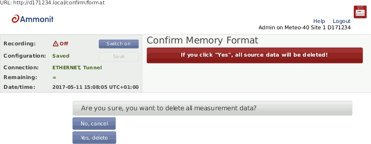
- Reset Data:
In order to delete all measurement data in one step, click on Delete all measurement data. The user will be asked to approve a confirmation prompt.
Important Recording stops after deleting measurement data. Start recording by clicking Switch on in the status box of the web interface.
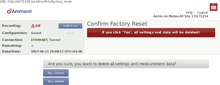
In order to delete all configurations, passwords and measurement data, click on Factory reset, delete all data. The data logger will be set back to the condition at delivery. The user will be asked to approve a confirmation prompt before the reset is performed.
Note After performing a factory reset, recording stops. Recording can be started after at least one sensor has been configured.
The data reset is logged in the Meteo-40 logbook.
- Scanning disk for errors
Used to scan the file systems of the data logger. Perform the scan only on demand of Ammonit. For further details, ask the Ammonit developers.


The development of Meteo-40 is in constant process. Ammonit is continually adding new features to the data logger according to user needs.
| Important |
|---|---|
In order to perform a software upgrade, the data logger has to be connected to the Internet, e.g., via modem or LAN or using the tethering function of a mobile phone ( Section 4.3.1, “Upgrade using a Smartphone”). It is not sufficient to connect Meteo-40 to a PC over USB, because a PC is not necessarily configured to work as a router. You have to be logged in as
If you do not have an Internet connection, you may upgrade the data logger offline, using a USB flash drive. See Section 4.3.3, “Offline Upgrade using USB Flash Drive” for details. |
- Update software list:
In this step the data logger browses for updates and displays the number of available software packages. Below the progress bar the currently installed version is displayed; the latest version describes the available upgrade.
Note The new software itself will not be downloaded and installed after clicking on Update software list. The software version is not changed in this step!
- Upgrade data logger software:
The software upgrade can easily be performed by pressing the Upgrade data logger software button. The software packages will be downloaded and installed.
After the installation is completed, CECS is restarted.
Note In older firmware versions the data logger has to be restarted after the upgrade. Press the Restart data logger button.
Important Before upgrading the data logger via modem, make sure that the corresponding switch is configured correctly in the → menu of the data logger web interface.
Depending on the installed firmware version, the software packages needed for the upgrade can be large. So the download and installation process can take some time depending on the speed of your Internet connection.
In rare cases the progress bar in the Meteo-40 web interface may seem to have stopped. Wait! If the progress bar does not move for a certain time, we recommend restarting the upgrade process.
Do not disconnect the power supply or reboot the system during the whole upgrade process.


The Meteo-40 data logger can only be upgraded when it is connected to the Internet.
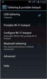
By connecting your smartphone to the data logger, you can set up an Internet connection via the tethering function of the smartphone.
Connect your smartphone to your Meteo-40 data logger via USB (USB-A slot of the data logger and micro USB slot of the smartphone). Make sure, that the data logger has no Ethernet LAN connection during the procedure, i.e. in doubt just unplug the Ethernet cable from the data logger. Open the settings for Tethering and portable hotspot of the smartphone operating system (see Figure 4.14, “Tethering Settings of an Android™ smartphone”) and activate USB tethering.
| Important |
|---|---|
Before starting the upgrade via tethering, make sure that Use DHCP for wired network is selected in the → menu of the Meteo-40 web interface. Additionally, make sure Connect to Internet via USB modem only is not selected in the → menu of the Meteo-40 web interface. |

Browse at Meteo-40 display for the IP address using the keys ( → → → → ). Enter the data logger's IP address in your smartphone browser, login and perform the upgrade.
![[Tip]](admon/tip.png) | Tip |
|---|---|
The tethering function can also be very useful for remote servicing. |
For most firewalls, that allow outgoing
HTTPS and
HTTP traffic, no special configuration is needed. Only in some very
restrictive environments, you may need to configure your firewall for the Meteo-40
software upgrade or ask your network administrator to do so. If Meteo-40 is in a
separated subnet, you may also need to specify a
Gateway in the LAN settings of the data logger.
Meteo-40 needs to connect the server
archive.ammonit.com via
HTTPS(port 443, since version 1.5) or
HTTP(port 80, before version 1.5) as outbound connection to perform a
software upgrade. Make sure, that these connections are allowed. There is no need for
Meteo-40 to connect any other servers, use any other protocols or use any kind of inbound
connections.
| Warning |
|---|---|
Note, that this method is not the preferred software upgrade method. If possible, please use the online upgrade method. Make sure, you have saved all your data and your configuration before performing an offline upgrade. |
Make sure, that all relevant data from data logger is saved: Configuration file, CSV files, and, if necessary, source data.
Make sure, the data logger has version
1.6or higher. Older versions of the data logger software do not support offline upgrade.Make sure, the software version you like to upgrade to is actually newer than the software version already installed on the data logger. Downgrades are not supported. Always use the latest offline update image from Ammonit, because errors of older versions might be fixed!
Download the latest version from here and unpack the zip archive. You will need the meteo-40.bin image file.
You need a prepared USB flash drive of at least
1 GiBcapacity. The flash drive must formatted asFAT32. The image file must be placed in the top-level of the flash drive, not in a directory. Further information is in theREADME.txtfile.
Switch off the CECS of the data logger. In doubt, remove the power supply.
Plug the prepared USB flash drive into one of the two USB-A slots of the Meteo-40.
If necessary, reconnect the power supply of the data logger. Switch on the CECS.
You will see the following text on the LC display:
Figure 4.15. Press the right arrow button
                          Found image
  for USB upgrade.
 Press the > button
     to proceed.
You have to press the right arrow button within ten seconds, otherwise the boot process continues normally and no upgrade will be performed.For around half a minute, the following message appears:
Warning After that step interrupting the process, unplugging the USB flash drive, or a power failure can lead to an non-functional data logger!
The complete process takes around eight minutes, until the following message appears:
which should be performed accordingly: Remove the power supply of the data logger, wait at least three seconds, remove the USB flash drive, and re-enable the power supply of the data logger.
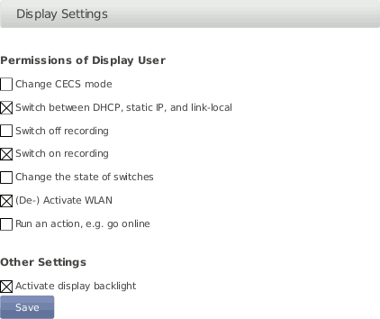
The display page shows, what can be seen on the LCD.
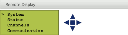
In order to give users without access to the web interface the chance of configuring the data logger, some permissions for display users can be selected, e.g., switch on recording or (de-)activate W-LAN.
If the corresponding permission Run an action is set, you can also start the execution of an action over the display menu → . Select one of the actions and press the right button to start it.
| Note |
|---|---|
To view the display in the web interface, it is advised to enable JavaScript in your web browser. |
Also on the device page, you can find a list of the USB devices, that are currently connected to the data logger and recognized by it, e.g. a modem, a flash drive, or a camera.
| Note |
|---|---|
The list of devices is not updated automatically. You have to reload the page to see any changes. |
Meteo-40 offers the possibility to download created CSV statistics files with measurement data (statistics see Section 6.3, “Statistic Data Files”), the source data in CSV format, and/or the logbook in CSV format to an USB flash drive. The USB flash drive must be connected to the data logger. Before you use this function, data logger and USB flash drive have to be configured.

| Important |
|---|---|
A file system like FAT32, NTFS, ext4, ext3, or ext2 is required on USB flash drive. |
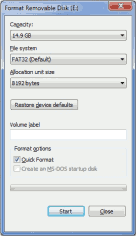
In order to format the USB flash drive with FAT32 on your
Windows™ PC, connect the USB stick to the PC. Open the
Windows™ Explorer. Right-click on the USB flash drive
shown under
Computer. Click on
Format... and select
FAT32 as
File system.
Start the formating process.
Create a file named keyfile.txt, which has to be saved on the
USB flash drive used to download CSV files (statistics and/or source data). This INI file
must include the data logger serial number and a password in a the INI file format. The
INI file is necessary to prevent unauthorized data download. Example:
[D123456]
password = yoursecretpassword
statistics = all
| Note |
|---|---|
The passphrase for the USB stick must have at least 8 characters! |
The passphrase has to be entered in the field shown in Figure 4.20, “Configuring the USB Flash Drive Copy”.
It is possible to use one USB flash drive for several data loggers. To do so, in
the
keyfile.txt the details of the data loggers have to be entered
section by section, e.g.,
[D123456]
password = passwordone
statistics = since 2016-01-01
gustdata = since 2016-01-01
config = save
logbook = all

[D234567]
password = passwordtwo
statistics = newest 10
config = save
sourcedata = all

[D345678]
password = passwordthree
statistics = month 2016-01
config = save
sourcedata = day 2016-01-07
The following entries are possible:
- password
Mandatory, must have at least eight characters
- statistics
One of the time period values, see below. Copies the primary statistics files.
- secondary
One of the time period values, see below. Copies the secondary statistics files.
- tertiary
One of the time period values, see below. Copies the tertiary statistics files.
- config
Value
saveto copy the configuration file. Other values are not yet implemented.- logbook
One of the time period values, see below.
- gustdata
One of the time period values, see below.
- sourcedata
One of the time period values, see below.
Warning Copying source data may take a very long time, even some hours.
The time period values are:
- all
Copy all files of this type.
- since DATE
Copy files of this type since and including DATE in format YYYY-MM-DD.
- until DATE
Copy files of this type until and including DATE in format YYYY-MM-DD.
- month DATE
Copy files of this type in the month of DATE in format YYYY-MM.
- day DATE
Copy files of this type at the day of DATE in format YYYY-MM-DD.
- newest NUMBER
Copy newest files of this type, max. NUMBER.
- oldest NUMBER
Copy oldest files of this type, max. NUMBER.
Meteo-40 has to be switched on for download. If the USB flash drive is configured
correctly, it will be recognized by the data logger. If the passphrase, entered in the
web interface and in the
keyfile.txt does not match, data download is not possible.
Meteo-40 shows in its display the number of downloaded files. When the download is finished, the data logger menu is shown and the USB flash drive can be disconnected.
By using this function, always all available files are copied to the USB flash drive. All data files are compressed to keep them as small as possible.
| Note |
|---|---|
If encryption and/or digital signature is switched on for the data logger, copying to the USB flash drive behaves accordingly, i.e. data will be encrypted and/or signed. If the option is enabled, copying source data to USB flash drive is prohibited. |
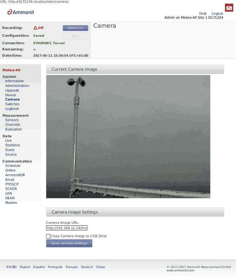
You can take pictures with Meteo-40 and send the image to AmmonitOR, as an email attachment, copy it to an SCP/FTP/SFTP file server or copy it to a permanently connected USB flash drive. Each of these options must be individually configured. See the respective checkboxes in the → , → , and → submenus.
You can either use a USB webcam plugged into one of the two USB-A slots or an Ethernet connected camera by HTTP/HTTPS.
| Note |
|---|---|
If the camera should be used for monitoring purposes, a steady power supply has to be connected. |
To take one or more photos with an outdoor camera, just enter the URL of the photo
in the web interface. The URL depends on the installed camera, e.g.,
http://
or
nn.nn.nn.nn/https://
. Mobotix M25M camera image URL
typically is
nn.nn.nn.nn/http://10.13.0.197/record/current.jpg.

If you connect the cammera via Ethernet, it is recommended to use static IP
addresses. You must configure both the camera and Meteo-40, each with a different address
in the same network. E.g.
10.13.0.197 for the camera and
10.13.0.200 for the data logger. In this case, the netmask would be
255.0.0.0. DNS server and gateway are not relevant here.
The static IP address of Meteo-40 can be configured in the → menu (see Section 7.7, “Configuring LAN Parameters”). In order to configure the IP address of the camera use the software delivered with it.
To minimize the energy consumption, the Ethernet port is not always active but is automatically activated only when needed, i.e. when the image has to be acquired and shared by means of one of the methods (AmmonitOR, email or SCP/FTP). This means, you might not see an image on accessing the → menu (see Section 4.5, “Using a Camera”) menu. You will know if the Ethernet interface is active because it will appear at the connections list in the status box of the web interface.
If you want the Ethernet port to be always active despite the higher power consumption, you can configure it in → menu (see Section 7.7, “Configuring LAN Parameters”).
In order to reduce the data traffic when a camera is sending pictures frequently,
we can restringe the modem tunnel communication to the scheduled online times. The option
Prevent implicit tunnel activation in menu
→ must be active. The option
Modem online whenever CECS is on (recommended) must not be
active.
| Important |
|---|---|
If a USB modem is connected to Meteo-40 and Ethernet is used for the camera, it
is necessary to select
|
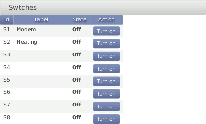
Switches can be used to control and optimize the power consumption of the measurement system. External devices connected to Meteo-40, such as modem, camera or heating can be controlled via the data logger. Meteo-40 will close (turn on) the configured switch when the correspondig device is needed, e.g., to send data via the modem connection, and open it again (turn off) when not needed.
In a solar power plant, a switch can be used to orient the solar trackers for protection of the payloads in case of high wind.
Meteo-40L data logger provides eight switches intended for the following tasks:
Control the modem power supply (recommended). See Section 7.9, “Configuring the Modem” for GSM and Section 7.7, “Configuring LAN Parameters” for satelite.
Control camera power supply. See Section 7.7, “Configuring LAN Parameters”.
Toggle sensor's power supply in case the polling rate is very low. See
Switch Pretimein Section 5.1.2, “Sensor Helper” and follow sensor specifications.Control one selected switch according to the configured measurements and thresholds Section 4.6.1, “Switch manager”.
A switch can only fulfill one of the duties. It can either be shared between several
sensors or used to control modem's power supply or at the
Switch Manager.
To manually toggle one or more of the switches individually, go to the → menu.
| Warning |
|---|---|
We highly recommend configuring a switch for the modem in the → menu. If the modem is switched manually via the → menu, you risk the shutdown of the modem after rebooting the data logger or after problems with the power supply. In Meteo-40 firmware version higher than 1.0 Rev.13915 switch S1 is set by default for the modem. In case the switch is not used for the modem, it can be deselected. |
| Note |
|---|---|
Refer to Chapter 13, Electrical Connection Plans for more information about physically connecting the supply using a switch. |
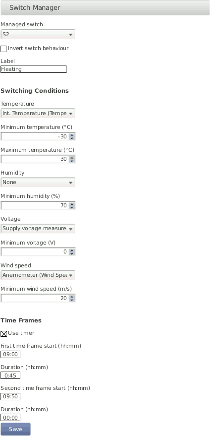
The
Switch manager is designed to automatically toggle
one of the switches depending on the configured conditions. It is
commonly used for sensor's heating control.
Only one switch can be selected.
In order to use this function, select a switch as well as one or more switching
conditions. The available switching conditions are temperature range, minimum humidity,
minimum voltage, minimum windspeed and two time frames. If more than one condition is
configured, the switch will only be closed (i.e.
On) when all conditions are fulfilled. If only one time frame is
needed, the duration of the second time frame duration must be set to 00:00. If the
inverted logic is selected, the switch will remain closed as long as the conditions are
not fulfilled. Only configured sensors and free switches are listed.
The state of the selected switch is reviewed according to the values calculated at the end of the configured statistics interval for SCADA, Switch manager and snapshots in the → menu. The default statistics interval is 10 min. The average value is used for temperature, humidity and voltage whereas the maximum is used for wind speed.
| Note |
|---|---|
If the state of the selected switch was manually changed, it will be overwritten by the switch manager at the end of the statistics interval. |
| Important |
|---|---|
It is necessary to keep the
CECS always on if the switch manager is deployed. The state of the
switch can only be closed (i.e.
|
If the sensor heating should be supplied by an external power supply via relay, check the connection plan Figure 13.17, “Electrical Connection Plan: Switch external Sensor Heating via Meteo-40 Switch Manager”.
Events, which are not related to measurement data, are listed in the logbook. The logbook displays for example all user logins and the user's IP address. A calendar is shown with a monthly overview. Green highlighted boxes indicate days with logbook entries. By clicking on the day, the entries are displayed. Click on the arrows shown above the calender to go to the previous or next month.
It is also possible to add entries to the logbook, e.g., to record replacements of sensors or any maintenance work that is important for data interpretation. Record messages by clicking on Log a message. A short text message can be edit.
Logbook entries of a day can be downloaded by clicking on the Download button.
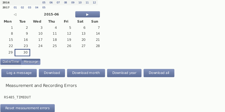
MARS errors are indicated by the red LED(second from bottom). A detailed list containing error codes is reported below Measurement and Recording Errors. By clicking on Reset Measurement Errors the list of errors can be deleted.
| Note |
|---|---|
The MARS error codes can be important for Ammonit engineers to locate errors in the data logger. |
The following actions or events are logged to the logbook:
User note to logbook
Log in of a user and failed login attempt
Factory reset
Memory format
Setting date and time via GPS, NTP, EKO sun tracker, SCADA or Admin (manually)
Setting location via GPS or EKO sun tracker
Copying data to USB flash drive
Software upgrade
Password reset by manufacturer
CECS start/stop
Actions execution
Actions initiated by a short message ( SMS)