Description
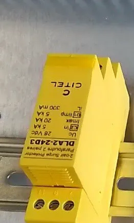
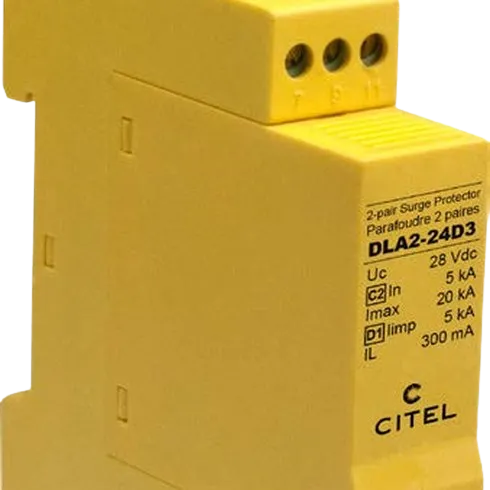
- 2-pair DIN rail plug-in Data surge protector
- Standards compliance: IEC 61643-21 / EN 61643-21
- Technology: GDT + Clamping diode
- Network: 4 … 20 mA
- Max. DC operating voltage: 28 VDC
- Max. discharge current : 5 kA
DLA protects information and communication technology, telecommunication equipment and data technology systems from lightning effects and surges.
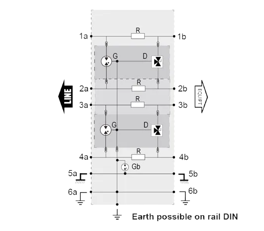
The electrical circuit of the DLA consists of a combination of high-performance gas discharge tubes and fast-switching diodes for high discharge capacity and fast response behaviour.
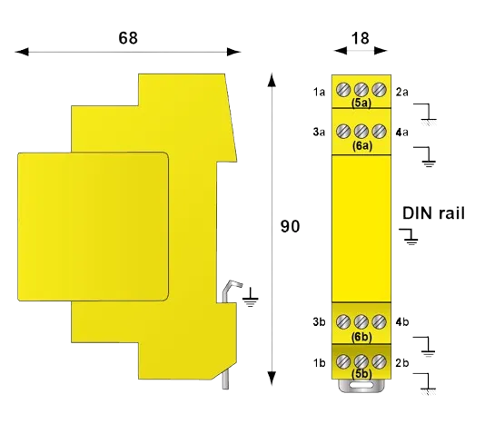
The shield connection is additionally earthed via a gas discharge tube. The earthing connection is conveniently made via the top-hat rail. When the plug-in module is unplugged, the transmission signal is not interrupted.