Description
Ammonit’s standard is heated version. It can be used for both heated and non-heated system.
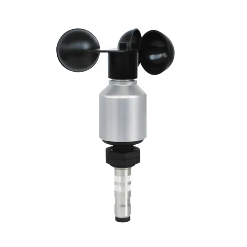
- Opto-electronic wind speed sensor
- “Low Power” – Frequency output signal
- Range 0.5 … 50 m/s
- Resolution < 0.1 m/s
Ammonit’s standard is heated version. It can be used for both heated and non-heated system.
| Anemometer Thies Compact | |
|---|---|
| General Information | |
| Order Number | S12100H |
| Measurement Principle | |
| Opto-electronic (slotted disc) | |
| Accuracy | |
| Accuracy | ± 3 % of meas. value, however ≥ 0.5 m/s |
| Resolution | < 0.1 m/s |
| Starting Velocity | 0.5 m/s |
| Operating Range | |
| Measurement Range | 0 … 50 m/s |
| Survival Wind Speed | max. 80 m/s (30 min) |
| Ambient Temperature | -40 … +70 °C |
| Electrical Data | |
| Electrical Supply | 9 … 30 V DC |
| Electrical Supply for Heating | 24 V AC/DC @ 20 W |
| General | |
| Connection | 7-pole plug-connection |
| Mounting | For example, onto mast tube with receptable thread Pg21 or boring Ø 29 mm |
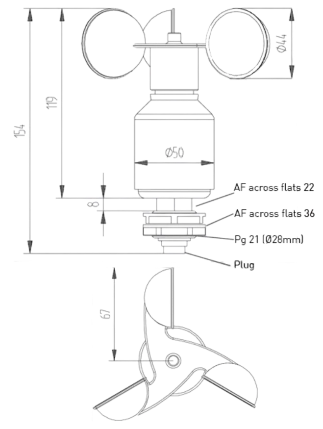
| Dimensions | 155 x Ø 134 mm |
| Weight | approx. 0.7 kg |
| Material | Housing: Aluminium Cup star: Synthetic with fibre glass |
| Type of Ball Bearings | Metallic ball bearings |
| Protection | IP 55 |
| Manufacturer | Thies |
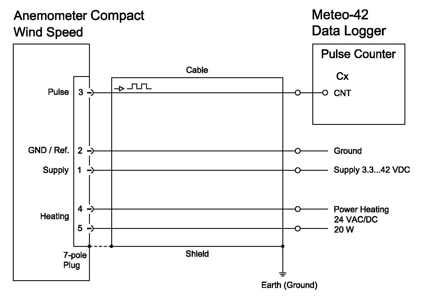
| Sensor connection diagram to Ammonit Meteo-42 Data Logger | ||||||||||||||||||||||||||||
 |
||||||||||||||||||||||||||||
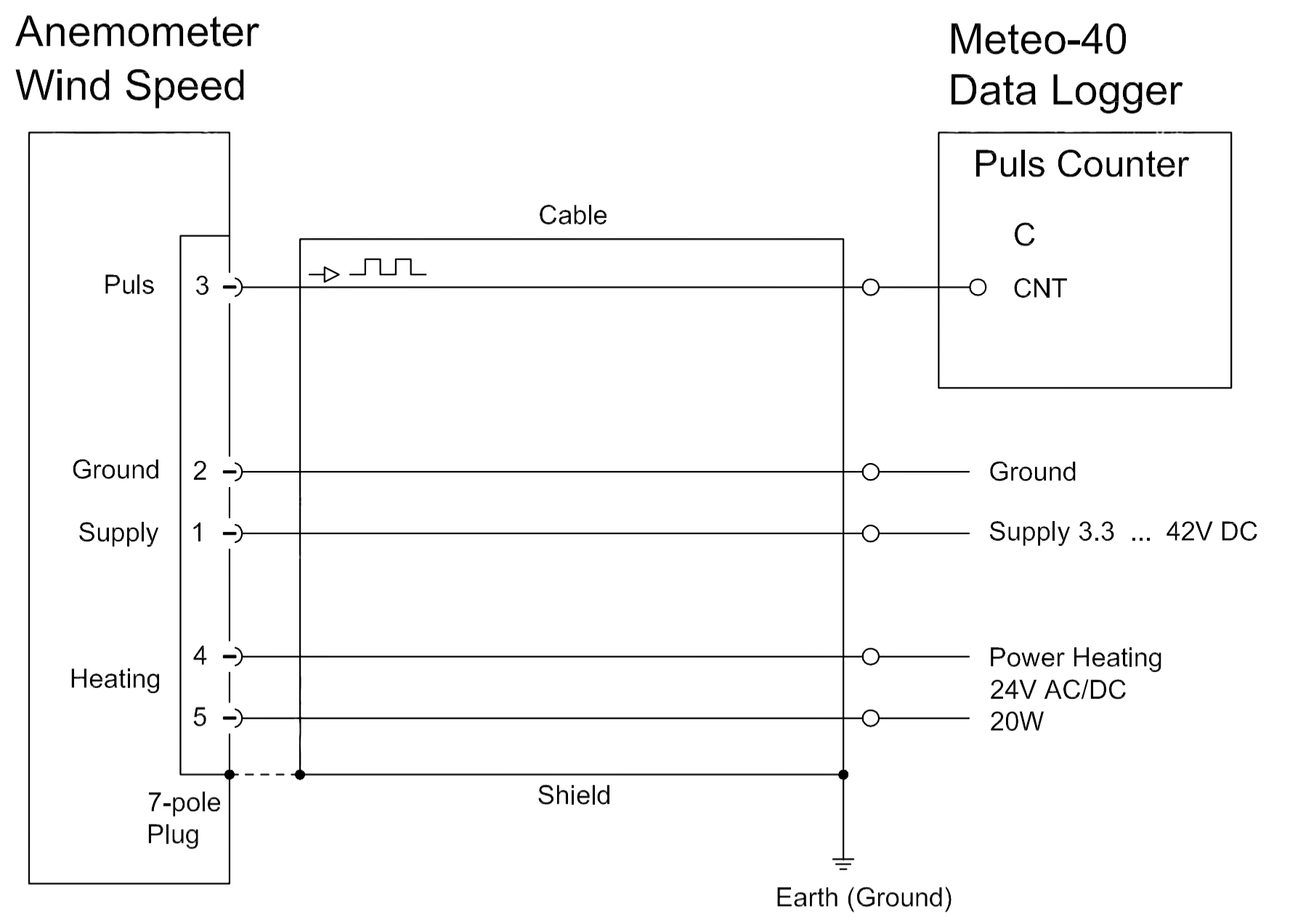
| Sensor connection diagram to Ammonit Meteo-40 Data Logger | ||||||||||||||||||||||||||||
 |
||||||||||||||||||||||||||||
|
||||||||||||||||||||||||||||
| * Supply voltage for usage with Meteo-40 data loggers. Cable type without heating wires: LiYCY 3 x 0.25 mm² Cable type with heating wires: LiYCY 7 x 0.25 mm² Connect the shield logger-sided to Ground (GND) |
| Coupling socket, Type: Binder, Serial 423, EMC with cable clamp | |
|---|---|
| Exploded View | |
 |
|
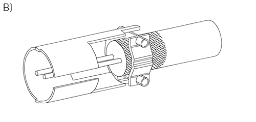
| Cable Connection: WITH Cable Shield | |
| Steps: 1. Stringing parts on cable according to plan above. 2. Stripping cable sheath 20 mm Cutting uncovered shield 15 mm Stripping wire 5 mm A) Putting shrink hose or insulation tape between wire and shield. |
 |
| B) If cable diameter permits, put the shield backward on the cable sheath.
3. Soldering wire to the insert, positioning shield in cable clamp. |
 |
| Cable Connection: WITHOUT Cable Shield | |
| Steps: 1. Stringing parts on cable according to plan above. 2. Stripping cable sheath 20 mm 3. Cutting uncovered shield 20 mm 4. Stripping wire 5 mm 5. Soldering wire to the insert 6. Positioning shield in cable clamp 7. Screwing-on cable clamp 8. Assembling remaining parts according to plan above 9. Tightening pull-relief of cable by screw-wrench (SW 16 and 17) |
 |