Anemometer Thies First Class Advanced X

Intelligent optically-scanned cup anemometer

Description

Classified according to IEC 61400-12-1 Edition 2.0 (2017-03)

The Thies FCA X Anemometer has the best classification values on the market.
Its built-in pressure sensor automatically corrects the wind speed measurement depending on air pressure.
The new low power version now has an even lower consumption (typ. 14 mA at 12 V) in IEC classified mode,
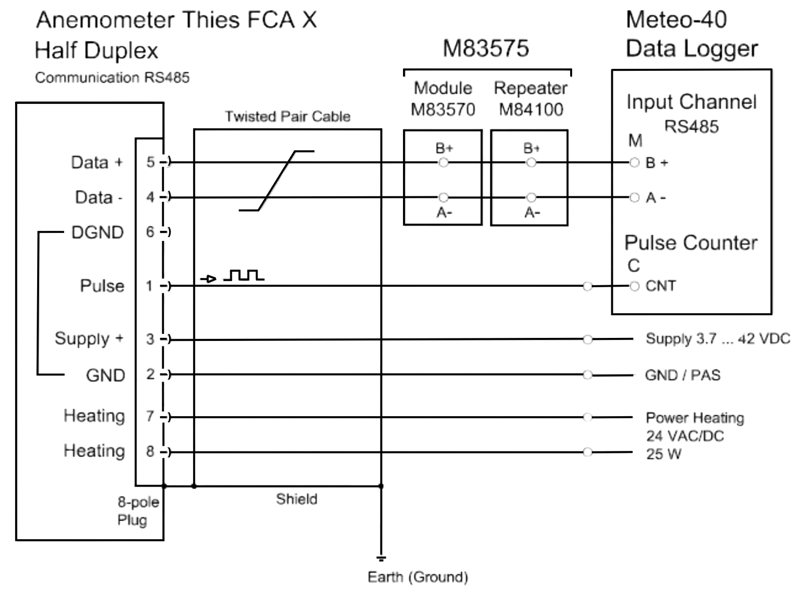
and up to eight sensors can be connected in a single bus.

Since the old version uses the same communication protocol as the new one, they can be used in the same bus.

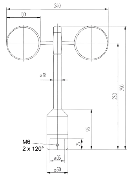
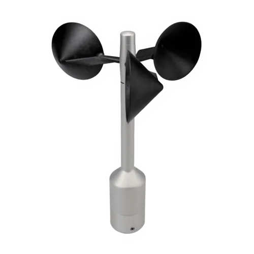
Intelligent Optically-Scanned Cup Anemometer

Thies First Class Advanced X is classified acc. to IEC 61400-12-1 Ed. 2.0 (2017-03). It has been designed to
measure:

  • Horizontal wind speed
  • Absolute and relative air pressure
  • Inclination X, Y and Z
  • Acceleration, frequency and amplitude of vibration measurement in X, Y and Z

The anemometer is designed for wind resource assessment and power curve measurements.
It offers minimal deviation from cosine line, optimized dynamic behavior under turbulence,
low overspeeding, low starting threshold, and excellent oblique inflow behavior.
The ball-bearing cup star ensures low maintenance, and electronically regulated heating supports winter operation.

Intelligent Correction of Measurement Values

The sensor integrates automatic wind speed correction based on air pressure (700 … 1100 hPa).
Output includes both original and corrected measurement values.

Calibration

For wind resource assessments, anemometers must be MEASNET-calibrated.
Thies First Class Advanced X can store calibration slope and offset values internally.
Recommended calibration: Ammonit Wind
Tunnel GmbH
.

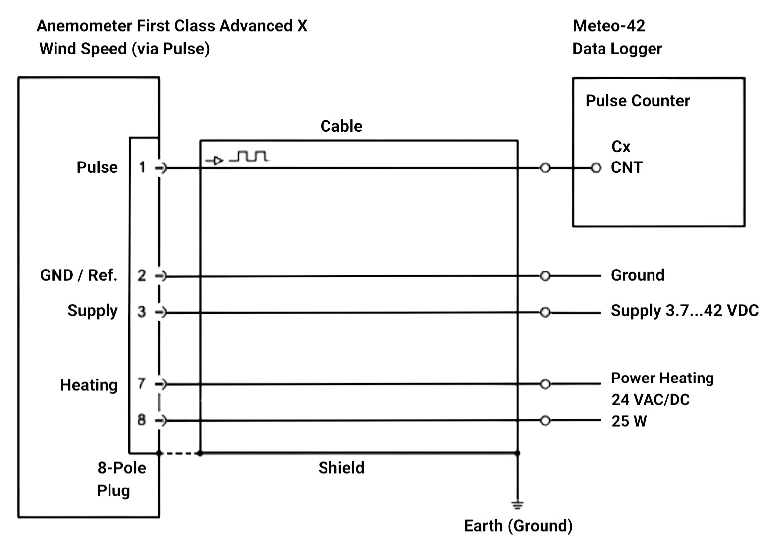
Configuration of Counter Output (IEC Classified Mode)

Parameter FO = 4: Counter output provides air pressure corrected wind speed for IEC classification.
Formula: wind speed [m/s] = 0.1 [m] × f [Hz]

Low Power Configuration (Heating OFF)

Default delivery: Low power configuration that also meets IEC classification.
Ideal for off-grid or limited-power scenarios.
Counter and serial outputs both provide air pressure corrected wind speed.

S Classification for Warm Climates

In regions where temperatures never drop below 10°C, the sensor in low power mode matches the IEC “Heating ON”
classification.

High Power Configuration (Heating ON)

For cold climates with sufficient power (up to 20W/sensor), request configuration for IEC mode with heating enabled.

Requires sensor version S11200H and special cable with heating cores.

Classification acc. to IEC 61400-12-1 Edition 2.0 (2017-03)

Air density effects were measured in a special wind tunnel setup (not via torque calculations).

Class A* Class B**
Heating ON 0.65 0.9
Heating OFF 1.1 1.8
Source: Summary report AK 151023-1.1 Cup Anemometer Classification, Deutsche WindGuard Tunnel Services GmbH,
Varel, Germany, 2017.

Operational Standard Uncertainty acc. to IEC 61400-12-1

Indicates max deviation at 10 m/s between real and measured wind speed:

Class A* Class B**
Heating ON 0.04 m/s 0.05 m/s
Heating OFF 0.06 m/s 0.10 m/s

Specifications

Anemometer Thies First Class Advanced X
General Information
Order Number S11201 / S11201H
Characteristics
Physical functionality Optically-scanned cup anemometer
Delivered signal Frequency output (pulse) and RS485 (Modbus)
Accuracy
Accuracy wind speed ±1% of measured value or < ±0.2 m/s @ 0.3 ... 50/s
Accuracy housing temperature ±1° (Measurement range: -40 ... +80 °C)
Accuracy air pressure ±1 hPa @ 20°C (Measurement range: 300 ... 1100 hPa)
Accuracy inclination (X, Y, Z) ±1° (Measurement range: -89.9° ... +89.9°)
Accuracy vibration (X, Y, Z) ±0.4 Hz (Measurement range: 0 ... 50 Hz)
Accuracy acceleration ±30 mg (Measurement range: ±8 g)
Linearity Correlation factor r between frequency f and wind speed y: r > 0.99999 (4 ... 20 m/s)
Starting velocity < 0.3 m/s
Resolution 0.05 m wind run
Distance constant < 3 m (acc. to ASTM D 5096 - 96) 3 m acc. to ISO 17713-1
Turbulent flow into cups Deviation Δv turbulent compared with stationary horizontal flow: -0.5 % < Δv < +2 %, Frequency < 2 Hz
Wind load Approx. 100 N @ 75 m/s
Operating Range
Measuring range 0.3 ... 75 m/s
Survival speed 80 m/s (min. 30 min)
Permissible ambient conditions -40 ... +80 °C, 0 ... 100% RH including condensation
Electrical Data
Output signal (frequency) Rectangle, 1082 Hz @ 50 m/s, supply voltage max. 15 V
Output signal (RS485) Modbus protocol, half duplex, data format: 8N1, Baud rate: 2400 to 57600
Supply for optoelec. scanning 3.7 ... 42 VDC, typical current 14 mA, max. 100 mA, 0.9 mA in power saving mode
Supply for heating (only S11201H) 24 V AC/DC, idle voltage max. 32 VAC / 48 VDC, power consumption 25 W
Mechanical
Connection 8-pole plug for shielded cable in the shaft
Mounting On mast tube R1" (Outer ≤ 34 mm, Inner ≥ 22 mm)
Dimensions 290 x 240 mm
Fixing boring 35 x 25 mm
Weight Approx. 0.5 kg
Material Housing: Anodised aluminium
Cup star: Carbon-fibre-reinforced plastic
Type of bearings Metallic ball bearings
Protection IP 55 (DIN 40050)
Patent EP 1 398 637, DE 103 27 632, EP 1 489 427
EMC EN 61000-6-2, EN 61000-6-3, EN 61010-1, EN 63000 2019-05
Manufacturer Thies
Accessory Module set M83575 (incl. isolated repeater)

Dimensional drawing

Sensor connection diagram

Sensor connection diagram to Ammonit Meteo-42 Data Logger
Sensor Plug Pin No. Ammonit Cable Wire Colour Meteo-40 Supply Sensor
Pulse 1 green CNT  
Data + 5 white B+  
Data - 4 brown A-  
Supply + 3 pink   3.7 ... 42 VDC*
GND 2 grey   GND / PAS
Heating 7 red   24 VAC/DC (25 W)
8 blue  
* Supply voltage for usage with Meteo-40 data loggers.
Cable type without heating wires: LiYCY 3 x 2 x 0.25 mm²
Cable type with heating wires: LiYCY 4 x 2 x 0.25 mm²
Sensor connection
Sensor Plug Pin No. Ammonit Cable Wire Colour Meteo-40 Supply Sensor
Pulse 1 green CNT  
Data + 5 white B+  
Data - 4 brown A-  
Supply + 3 pink   3.7 ... 42 VDC*
GND 2 grey   GND / PAS
Heating 7 red   24 VAC/DC (25 W)
8 blue  
* Supply voltage for usage with Meteo-40 data loggers.
Cable type without heating wires: LiYCY 3 x 2 x 0.25 mm²
Cable type with heating wires: LiYCY 4 x 2 x 0.25 mm²
Sensor connection diagram to Ammonit Meteo-40 Data Logger
Sensor Plug Pin No. Ammonit Cable Wire Colour Meteo-40 Supply Sensor
Pulse 1 green CNT  
Data + 5 white B+  
Data - 4 brown A-  
Supply + 3 pink   3.7 ... 42 VDC*
GND 2 grey   GND / PAS
Heating 7 red   24 VAC/DC (25 W)
8 blue  
* Supply voltage for usage with Meteo-40 data loggers.
Cable type without heating wires: LiYCY 3 x 2 x 0.25 mm²
Cable type with heating wires: LiYCY 4 x 2 x 0.25 mm²
Connection recommendations for the cable shield
Sensor carrier Sensor Shielding / Ground
Metallic met mast, grounded Non-isolated mounting on the met mast (e.g. by using metallic brackets, holders, etc.) Connect cable shield only at the side of the data logger to ground.
Metallic met mast, grounded Isolated mounting at the met mast (e.g. by using non-metallic brackets, holder etc. or metallic brackets, holders etc. with isolated plastic adapters)

Connect cable shield at sensor plug and at the side of the data logger to ground.

Metallic met mast, non-grounded Non-isolated mounting on the met mast (e.g. by using metallic brackets, holders etc.)

Instructions

Coupling socket, Type: Binder, Serial 423, EMC with cable clamp
Exploded View
Exploded view of connector
Cable Connection: WITH Cable Shield

Steps:
1. Stringing parts on cable according to plan above.
2. Stripping cable sheath 20 mm
    Cutting uncovered shield 15 mm
    Stripping wire 5 mm

A) Putting shrink hose or insulation tape between wire and shield.

Cable with shield A

B) If cable diameter permits, put the shield backward on the cable sheath.

3. Soldering wire to the insert, positioning shield in cable clamp.
4. Screwing-on cable clamp.
5. Assembling remaining parts according to plan above.
6. Tightening pull-relief of cable by screw-wrench (SW 16 and 17).

Cable with shield B
Cable Connection: WITHOUT Cable Shield
Steps:
1. Stringing parts on cable according to plan above.
2. Stripping cable sheath 20 mm
3. Cutting uncovered shield 20 mm
4. Stripping wire 5 mm
5. Soldering wire to the insert
6. Positioning shield in cable clamp
7. Screwing-on cable clamp
8. Assembling remaining parts according to plan above
9. Tightening pull-relief of cable by screw-wrench (SW 16 and 17)
Cable without shield

Accessories