Description
Classification acc. to IEC 61400-12-1 Edition 2.0 (2017-03)
Class A and B
| Class A* | Class B** | |
|---|---|---|
| Heating ON or temperature range: 15 … 40° C |
1.8 | 2.0 |
| Heating OFF | 2.3 | 2.7 |
*Class A: simple terrain (-3 … 3° tilt) (low turbulences) (0° … 40°C)
**Class B: complex terrain (-15 … +15° tilt) (high turbulences) (-10° … 40°C)
Source: Classification report Class A and B
Class S for different air temperatures
| -10°C | -5°C | 0°C | 5°C | 10°C | 15°C | 20°C | 25°C | 30°C | |
|---|---|---|---|---|---|---|---|---|---|
| Class ‘S’ | 2.8 | 2.6 | 2.3 | 2.1 | 1.9 | 1.8 | 1.8 | 1.8 | 1.8 |
The Class S is obtained using the same classification parameters as for Class A with the exception of the
temperature.
Source: Classification report Class S temperature
Operational Standard Uncertainty acc. to IEC 61400-12-1
The operational standard uncertainty describes the maximum deviation of the wind speed measured by the anemometer
compared with the real wind speed. The table indicates the operational standard uncertainty at 10 m/s:
| Class A* | Class B** | |
|---|---|---|
| Heating ON or temperature range: 15 … 40° C |
0.10 m/s | 0.12 m/s |
| Heating OFF | 0.13 m/s | 0.16 m/s |
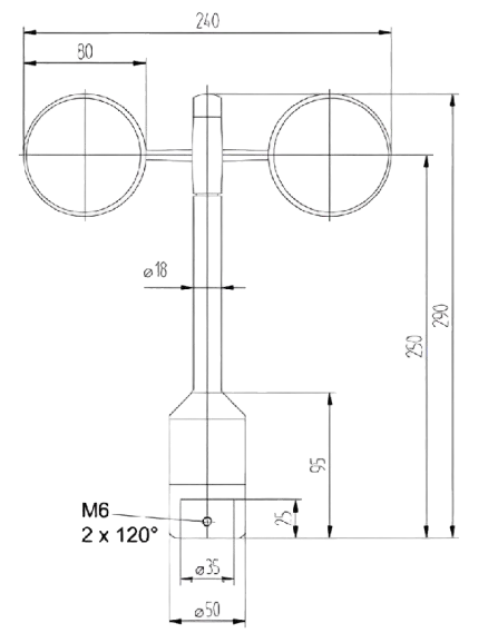
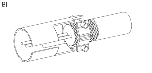
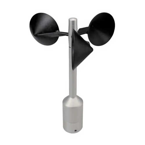
Optically-scanned cup anemometer
Thies First Class Advanced gives outstanding performance. The sensor has been classified acc. to IEC 61400-12-1 Edition
2.0. It gives optimal dynamic performance with the following characteristics:
- High accuracy
- Minimal deviation from cosine line
- Excellent behaviour to turbulences
- Minimum overspeeding Small distance constant
- Low start up value
- Low power consumption
- Digital output
The sensor is designed for measuring the horizontal wind velocity in the field of meteorology, climate research, site
assessment, and the measurement of capacity characteristics of wind power systems (power curves). The patented design is
the result of long testing in the wind tunnel. The sensor features dynamic behaviour also at high turbulence intensity,
minimal overspeeding, and a low starting values. It requires only low maintenance thanks to its low-inertia and
ball-bearing cup star. The anemometer is equipped with electronically regulated heating to guarantee smooth running of
the ball bearings and prevent icing of shaft and slot during winter operation.